
An industrial membrane switch is a thin, sealed user-interface assembly that combines a printed graphic overlay, adhesive and spacer layers, a flexible or rigid circuit, and optional metal domes, backlighting and shielding. A reliable design starts with the machine environment and electrical interface, then fixes the stack-up, key geometry, tail, connector, adhesive zones and acceptance tests on controlled drawings. The complete assembly, rather than one material alone, determines tactile response, sealing and service life.
What Is an Industrial Membrane Switch?
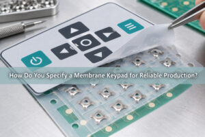
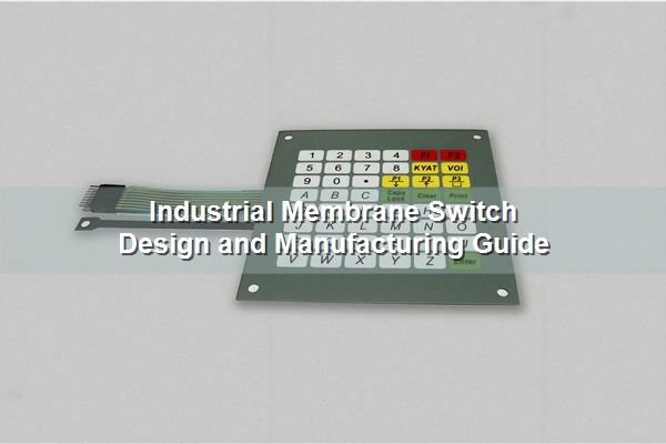
An industrial membrane switch converts a press on a printed control surface into an electrical input while keeping the interface thin and easy to seal. It can be a simple non-tactile printed contact, a tactile metal-dome key, or a mixed panel that also carries windows, LEDs, shielding and a flexible tail. The term describes the complete switch assembly, not just the top graphic film.
Industrial designs are normally released around the actual equipment: enclosure opening, mounting surface, key spacing, connector location, input-circuit limits, cleaning agents, temperature range and operator use. A generic sample can demonstrate feel, but it cannot validate the final stack.
When Is a Membrane Switch Better Than Mechanical Buttons or a Touchscreen?
A membrane switch is often preferred when the panel needs a low profile, a continuous cleanable surface, custom legends and several keys in one bonded assembly. Mechanical switches remain useful when long travel, replaceable individual parts or high switched loads are required. Touchscreens suit changing graphics and dense menus, but they may need separate tactile controls for gloved or eyes-free operation.
| Interface | Strong fit | Design limitation to check |
|---|---|---|
| Industrial membrane switch | Thin sealed panel, fixed functions, custom graphics, integrated tactile keys | Fixed legends and key locations; tail and adhesive are part of the design |
| Discrete mechanical buttons | Long travel, individual replacement, high-force operation | More panel depth and sealing hardware |
| Touchscreen | Dynamic interface, many screens, software-defined controls | Glove response, visibility, impact protection and tactile confirmation |
What Layers Define the Switch Stack-Up?
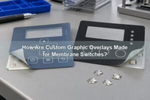
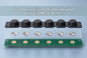
The stack-up defines how load, travel, electrical contact and environmental sealing work together. A common construction uses a printed polyester or polycarbonate overlay, overlay adhesive, a spacer or retainer layer, a circuit layer and a rear mounting adhesive. Metal domes, light-guide film, shielding and stiffeners are added only where the product requires them.
| Layer or feature | Primary function | Release item |
|---|---|---|
| Graphic overlay | Legends, colors, windows and operator surface | Artwork, material, finish and embossing geometry |
| Overlay adhesive | Bonds the graphic layer without restricting key motion | Adhesive family, cutouts and bond area |
| Spacer or dome retainer | Creates travel cavity and controls dome position | Opening size, vent path and registration datum |
| Circuit | Routes switch contacts to the tail or connector | Gerber or circuit drawing, conductor system and test limits |
| Rear adhesive | Mounts the complete switch to the equipment | Target surface, adhesive coverage and assembly process |
Printed Silver PET vs Copper Flex vs PCB Circuits
Printed silver on PET is widely used for cost-sensitive membrane circuits with moderate routing density. Copper flex supports finer conductors, plated features and more conventional connector interfaces. A PCB-backed switch adds stiffness and can carry components, but it increases thickness and changes how the panel follows the enclosure.
| Circuit option | Use it when | Confirm before release |
|---|---|---|
| Printed silver PET | Routing is simple and a thin flexible circuit is required | Trace resistance, crossover construction, tail bend and connector contact system |
| Copper FPC | Routing density, fine pitch or plated termination drives the design | Copper weight, coverlay openings, bend radius and stiffener |
| Rigid PCB | Components, rigid mounting or board-level integration are needed | Board thickness, support, dome pad finish and enclosure tolerance |
How Are Metal Domes Integrated Into the Switch?
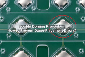
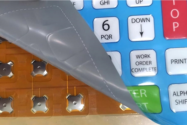
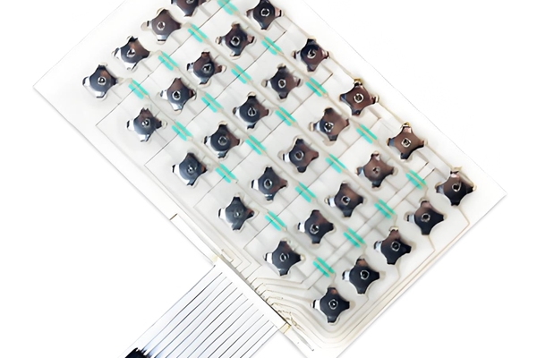
A metal dome is centered over its matching circuit contacts and retained so that later lamination and handling do not shift it. The actuator should load the intended region, the spacer should allow snap travel, and the adhesive must stay outside the active dome area. The dome force printed on a component drawing is not automatically the force an operator feels through the completed overlay.
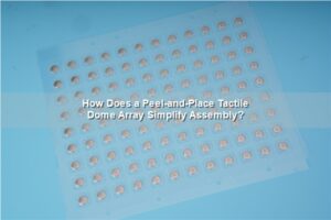
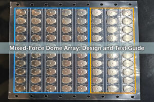
For a multi-key layout, a custom dome array can hold the specified domes at controlled center coordinates. We review the dome outline, force target, PCB contact drawing, actuator geometry and carrier datum together because each part affects assembled response.
Which Drawing Dimensions Control Layer Registration?
Registration depends on a common datum system across the overlay, spacer, circuit, dome carrier and enclosure. The drawing should dimension key centers, window edges, circuit contacts, tooling holes, panel outline and tail exit from the same functional datums. Chained dimensions can hide accumulated error across a long panel.
Also define which layer controls the finished outline and which features are inspected after lamination. A good tolerance table distinguishes single-layer cutting capability from the realizable alignment of the complete bonded stack.
How Should Spacer Openings, Vent Paths and Adhesives Work Together?
The spacer opening must give the dome or contact enough room to move without creating an unnecessary weak edge. Air displaced during a press needs a controlled path when the key cavity would otherwise be trapped. The route can connect adjacent cavities or lead to a protected internal area, but it should not create a direct contamination path from the panel edge.
Adhesive coverage should be continuous where sealing and mounting require it, with deliberate keep-outs around moving contacts, windows and vents. Specify the enclosure surface material, texture and cleaning method because bond performance depends on the actual mating surface and assembly pressure.
How Should the Tail, Connector and Strain Relief Be Specified?
The tail is part of the electrical and mechanical interface. Specify exit location, length, conductor pitch, exposed-contact orientation, contact side, stiffener geometry and connector series. Mark the no-bend zone at the panel exit and connector, then check the installed routing against the enclosure rather than judging the flat drawing alone.
If the assembly uses printed silver contacts, confirm that the chosen connector is compatible with that contact system. For copper flex, define plating and stiffener requirements from the connector specification. A pull or repeated bend at the tail transition can damage conductors even when the key area remains intact.
How Are Backlighting and EMI Shielding Integrated?
Backlighting must be coordinated with legends, light-blocking layers, key travel and circuit routing. A dome array with light-guide film can distribute light through a thin stack, but LED position, film pattern and opaque printing still need prototype evaluation for brightness uniformity.
EMI control can use a conductive layer connected to an identified ground point. Our EMI dome-array construction is relevant when the interface requires a defined shielding path. The drawing should identify the shield area, insulation clearances, ground termination and any window or tail region where shielding is interrupted.
How Is an Industrial Membrane Switch Manufactured?
Production converts approved artwork, circuit data and stack drawings into individually inspected layers, then aligns and laminates them into one assembly. The exact route depends on the circuit technology, but the control points remain traceable from printing or imaging through cutting, dome placement, lamination and final test.
- Verify artwork, colors, windows and legend registration against the approved file.
- Produce and inspect the circuit before it is hidden inside the stack.
- Cut spacers, adhesives and carriers with the released openings and datums.
- Place domes and optional lighting or shielding features using the defined alignment method.
- Laminate under controlled pressure, protect the tail and inspect the finished outline.
- Perform electrical, visual and specified mechanical checks before packing.
Which Electrical and Mechanical Tests Belong in the Control Plan?
The control plan should connect every test to a drawing requirement. Circuit continuity and isolation confirm routing, while contact resistance or logic-level closure checks the actual switch path under stated conditions. Mechanical checks may include assembled operating force, travel, return, tail pull, adhesive peel or dimensional inspection where these affect the product.
| Requirement | Test record | What it does not prove by itself |
|---|---|---|
| Correct circuit routing | Continuity and isolation result | Key feel or environmental sealing |
| Reliable key closure | Defined resistance or logic threshold during actuation | Long-term life without cycling evidence |
| Specified tactile response | Force and travel measured on the stated assembly | Electrical closure unless it is logged at the same time |
| Layer alignment | Critical dimensions and visual registration | Bond durability on an unqualified enclosure surface |
How Should Environmental Validation Match the Machine?
Validation should reproduce the hazards the installed panel will actually see: temperature and humidity cycling, cleaning chemicals, UV exposure, glove use, dust, splash, vibration or repeated actuation. A material datasheet can support selection, but it does not validate the cut edges, adhesive bonds, windows, tail exit and enclosure interface of the finished product.
Define the test state and pass criteria before prototypes are built. If ingress protection is a system requirement, evaluate the installed panel and enclosure together; a switch sample alone cannot establish the rating of the complete machine.
What Files Are Needed for a Prototype?
A useful prototype package defines the assembly well enough to build and evaluate the intended product. Send the overlay artwork, panel and key dimensions, circuit schematic or Gerbers, tail and connector requirement, stack or material preference, dome force target, lighting or shielding needs, environmental conditions and prototype quantity. Include the enclosure drawing or mounting-surface details when fit and adhesive performance matter.
We use those files to identify missing tolerances, incompatible stack assumptions and the prototype checks needed before production. If the circuit architecture or dome type is still open, mark it as a design decision instead of locking an unverified construction into the request.
Industrial Membrane Switch FAQs
What does a membrane switch do?
It provides a printed operator interface and closes an electrical circuit when a defined key area is pressed. The same assembly can also carry tactile domes, windows, backlighting and shielding.
Are industrial membrane switches always tactile?
No. They can use non-tactile printed contacts, embossed overlays, metal domes or combinations. The tactile method should be selected from the required feel, travel, electrical design and assembly thickness.
Can a membrane switch be waterproof?
The switch can be designed with sealed layers and a protected tail exit, but the final ingress rating belongs to the installed switch and enclosure. Edges, connectors, mounting surfaces and openings must be validated together.
What is the difference between a membrane switch and a membrane keypad?
A membrane switch emphasizes the electrical switching assembly. A membrane keypad usually describes the operator-facing multi-key interface. In many products the same finished part can correctly be described by both terms.
For an industrial membrane switch, the fastest route to a useful prototype is a controlled stack drawing plus the real enclosure, electrical and environmental requirements. To request a quote, send us the overlay artwork, circuit files, dome and tail specifications, operating environment, prototype quantity and expected production volume. We can review the dome array, circuit, adhesive and optional lighting or shielding as one assembly. Contact EBest Circuit(Best Technology) at sales@metal-domes.com.