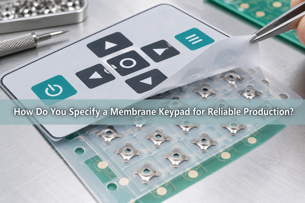
A Membrane Keypad is a low-profile user interface that closes printed electrical contacts when a key is pressed. Its graphic overlay, adhesive, spacer, circuit and tactile element must operate as one controlled stack. At EBest Circuit(Best Technology), we manufacture custom keypad and metal-dome assemblies from the customer’s mechanical, electrical, tactile and environmental requirements. This guide shows which decisions must be fixed before the design is ready for reliable production.
What Is a Membrane Keypad?
A membrane keypad is a thin switch assembly in which flexible layers form the legends, moving contact system and mounting interface. The terms membrane keypad switch and membrane switch keypad are often used for the same product family. A flexible membrane keypad may use printed contacts, polyester domes or stainless-steel metal domes, depending on the required tactile response and life target.
Unlike a desktop membrane keyboard, an industrial keypad is designed around a specific enclosure, circuit connection and operating environment. The number of keys, key pitch, tail exit, connector, surface graphics and seal are customized for the equipment. The product is therefore an engineered interface, not only a printed label placed over switches.
How Does a Membrane Keypad Work?
A membrane keypad works by using pressure to bridge two conductive regions and momentarily close a circuit. When the user releases the key, the elastic layer or dome returns to its original position and the contact opens. The controller then interprets the individual line or row-and-column combination as an input.
In a tactile construction, a metal or polyester dome supplies the snap that tells the user the key has actuated. In a non-tactile construction, the overlay or upper circuit flexes toward a lower printed contact without a snap element. Light, sound or a display response may then confirm operation. The circuit logic and mechanical feel should be selected separately because one does not guarantee the other.
Which Layers Make Up the Keypad Stack?
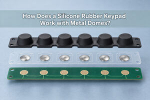
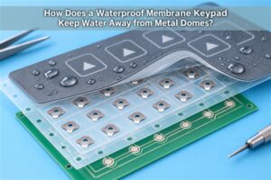
The layer stack determines the finished height, force path, seal and circuit behavior. A common construction includes a graphic overlay, overlay adhesive, dome retainer or upper circuit, spacer, lower circuit and rear mounting adhesive. A rigid backer can be added when the assembly cannot rely on the customer’s enclosure for support.
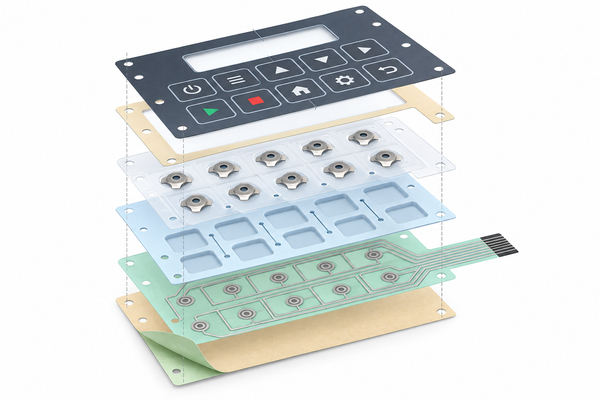
| Layer | Main job | Production input |
|---|---|---|
| Graphic overlay | Legends, key zones, windows and surface protection | Film grade, texture, artwork, embossing and window definition |
| Overlay adhesive | Bonds the face layer without blocking key movement | Coverage, thickness, environmental exposure and cutouts |
| Dome retainer or upper circuit | Locates tactile elements or carries printed contacts | Key centers, dome type, venting and electrical pattern |
| Spacer | Maintains separation and creates key cavities | Thickness, air paths and dielectric clearance |
| Lower circuit | Routes switch signals to the tail | Silver/carbon pattern, matrix, trace width and connector |
| Rear adhesive or backer | Mounts and supports the finished keypad | Housing material, surface finish, liner and assembly datum |
We review the stack as a dimensioned assembly. A material list without thicknesses, cutouts and datum relationships is not enough to protect key feel or registration.
Which Tactile Option Should You Select?
The tactile option should match the user’s feedback requirement, available height, force window and operating environment. Flat contacts create the thinnest construction but offer little mechanical feedback. Polydomes provide a formed polyester response, while metal domes deliver a sharper snap and can be specified by geometry, force, travel and click ratio.
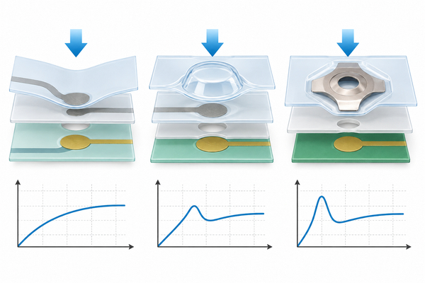
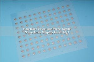
Our polydome versus metal dome array comparison helps separate the two tactile routes. If several key positions must be installed together, we can build a custom dome array that registers the selected domes to the PCB or printed circuit. When the mechanical key cannot load the dome directly, a plunger dome array can add a controlled actuator between the key and dome.
A tactile membrane keypad must be evaluated as a force path. A high trip force does not automatically create a strong perceived click if the overlay, actuator or enclosure absorbs travel.
How Should Key Geometry, Force and Travel Be Specified?
Key geometry should define where force enters the stack and how accurately it is centered on the contact. The drawing should show the active key area, center coordinates, pitch, emboss outline, actuator diameter, support surface and permitted over-travel. These dimensions control feel more reliably than a visual artwork file alone.
For metal-dome constructions, specify trip force, return force or click ratio when it matters, travel, dome shape and the force tolerance accepted across keys. Our dome-array portfolio can combine different sizes, shapes and force values on one carrier when the interface needs distinct key behavior. Final values remain subject to the selected dome series, stack and test method.
During membrane keypad design, we also check edge loading. A keycap or emboss that is much larger than the actuator can tilt, while a very small contact point can concentrate force and damage the overlay. The goal is repeatable centered actuation, not simply fitting the dome inside the artwork.
What Circuit, Tail and Connector Details Must Be Released?
The circuit drawing must identify every switch node, common line, matrix relationship, tail conductor and termination. A membrane matrix keypad can reduce the number of tail conductors, but the controller must manage ghosting and rollover requirements. Individual circuits are simpler to interpret but may need a wider tail.
- Show the contact-pad geometry and the center shared with each tactile element.
- Define tail length, exit direction, bend zones, stiffener and connector contact side.
- State the connector part number or mating interface, not only the pin pitch.
- Mark keepout areas around windows, LEDs, fasteners and enclosure ribs.
- Define any shielding layer and its actual ground connection.
When the interface needs electrostatic control, an EMI metal dome array can add conductive printing to the array construction. The layer must still connect to a defined ground path; conductive ink without a system connection is not a complete EMI solution.
How Do Adhesives, Venting and Sealing Affect Reliability?
Adhesive and venting determine whether the keypad stays attached and whether each dome can move freely. The rear adhesive must match the real enclosure material and finish. The dome-retainer adhesive must hold the array without creeping into the active contact or air path.
A vent channel lets displaced air move when a key is pressed. A sealed cavity can raise apparent force, slow return or make adjacent keys interact. Venting should therefore be designed inside the protected stack rather than created as an uncontrolled opening to the outside environment.
For additional retention beneath flexible key layers, we can evaluate a rubber-glue metal dome array. A waterproof membrane keypad also requires an enclosure-level sealing plan, protected tail exit and verified edge construction. Readers who need a dedicated ingress-control path can use our existing waterproof-keypad guide; this article keeps sealing in its proper role within the complete production specification.
How Should the Graphic Overlay and Backlighting Be Designed?
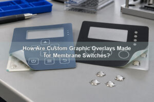
The graphic overlay must align printed legends, embossed keys and transparent windows with the mechanical and electrical stack below. PET or polycarbonate film, reverse-side printing, texture and hard coating are selected according to flexing, cleaning, abrasion and optical requirements. The approved artwork should share the same key-center datums as the circuit drawing.
Backlighting can use discrete LEDs, electroluminescent material or a light-guide film, depending on space and brightness needs. Dead-front icons need a specified on-state and off-state appearance. Light leakage, diffuser coverage, LED hot spots and the color of surrounding printed layers should be checked on an assembled prototype.
For thin illuminated assemblies, our LGF dome array integrates a light-guide-film route with registered metal domes. We coordinate light distribution with dome height, adhesive openings and key geometry so the optical layer does not interfere with actuation.
How Is a Custom Membrane Keypad Manufactured?
A custom membrane keypad moves from controlled artwork and mechanical data into printing, curing, cutting, circuit fabrication, tactile-element placement, lamination and final inspection. The sequence depends on whether the circuit is printed PET, FPC or PCB based and whether the interface includes metal domes, polydomes, LEDs, shielding or a rigid backer.
Our keypad membrane switch manufacturing review begins before tooling. We compare the artwork, circuit, enclosure and dome-array files for common datums and conflicting dimensions. During production, registration, print quality, electrical continuity, dome force, key operation and finished outline are checked against the approved sample and drawing.
A membrane keypad manufacturer should also control revision identity. Overlay artwork, circuit pattern, adhesive cut file and assembly drawing must change together. Mixing one revised layer with an older layer can create a visually correct part that fails electrically or mechanically.
How Should the Prototype Be Tested Before Production?
The prototype should be tested as an assembled interface on the intended support surface. A loose keypad on a bench can feel different from one mounted to a rigid enclosure. We therefore recommend confirming appearance, key registration, actuation, return, circuit output and adhesion on production-equivalent parts.
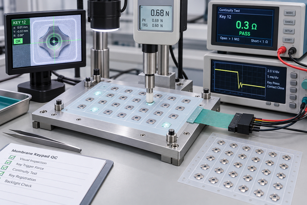
- Measure representative key force and return behavior using the agreed actuator and support.
- Verify every circuit and matrix combination, including the connector pinout.
- Inspect artwork, windows, embossing, outline and key-center alignment.
- Check lighting uniformity, icon readability and unintended light leakage.
- Run applicable temperature, humidity, cleaning, adhesion and cycle tests.
- Record the approved sample and drawing revision before volume production.
Test conditions must match the product risk. A laboratory life result on a bare dome does not automatically represent the finished keypad, and a cosmetic sample does not prove electrical reliability.
Which Applications Benefit from Membrane Keypads?
Membrane keypads suit equipment that needs a low profile, custom graphics and a cleanable user surface. These membrane switch keypads are common in industrial controls, medical instruments, test equipment, automotive controls, access systems, appliances and handheld electronics. Each field places a different weight on tactile feedback, chemical resistance, sealing, lighting and connector design.
Industrial controls may prioritize gloves, clear status indication and secure mounting. Medical equipment may require controlled cleaning compatibility and easily verified key response. Automotive or handheld products may place more emphasis on temperature cycling, vibration, backlighting and compact tail routing. We translate the application into measurable material and validation inputs rather than claiming one stack suits every industry.
What Should You Include in a Membrane Keypad RFQ?
A membrane keypad RFQ should give the manufacturer enough information to quote the intended assembly instead of guessing from an image. For a useful review, send the following:
- Dimensioned outline and enclosure drawing with key centers and mounting datums.
- Vector graphic artwork, colors, surface finish, windows and embossing details.
- Circuit schematic or Gerber/PDF data, tail drawing, pinout and connector specification.
- Tactile preference, target force, travel, expected key-use profile and actuator geometry.
- Operating environment, cleaning chemicals, sealing target and relevant compliance needs.
- Backlighting, shielding, LED and display-window requirements.
- Prototype quantity, annual volume, inspection plan and required validation tests.
Send these files to sales@metal-domes.com or use our quotation form. We will review the stack, shared datums, tactile path and test requirements before recommending materials or tooling. That is how a Membrane Keypad moves from an interface concept to a controlled, production-ready assembly.