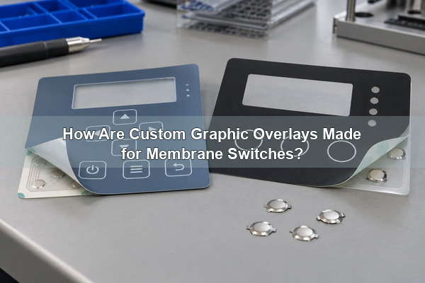
Custom graphic overlays are the printed, user-facing films that identify controls, protect the interface and guide every key press on a membrane switch. A dependable overlay is not merely a decorated label. Its film, ink, windows, embossing, adhesive and registration must work with the circuit, enclosure and metal-dome system beneath it. At EBest Circuit(Best Technology), we design these elements as one interface so that appearance, tactile response and assembly alignment support the same product requirement.
What Are Custom Graphic Overlays?
A custom graphic overlay is a thin printed polyester or polycarbonate face layer made to match a specific product. It carries legends, icons, safety information, branding, key boundaries and transparent display areas. It can remain flat, or it can include formed key zones that help users locate controls by touch.
The overlay also separates the operating environment from the electrical layers below. Reverse-side graphics are viewed through the clear film, so normal finger contact and routine cleaning do not directly rub the ink. The film itself becomes the first mechanical and optical barrier.
This distinction matters when comparing industrial overlays with ordinary decals. A membrane-switch overlay must control registration, key feel, window clarity, adhesive cutouts and compatibility with repeated actuation. It is a functional component of the human-machine interface.
Where Does a Graphic Overlay Fit in a Membrane Switch?
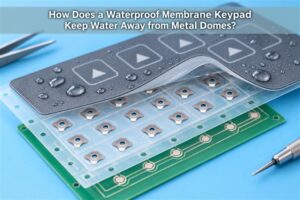
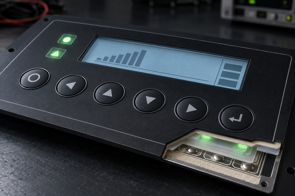
The overlay is the top layer of a membrane-switch stack. Beneath it may be a graphic adhesive, an upper circuit or dome-retainer layer, a spacer, a lower circuit and a rear mounting adhesive. A custom graphic overlay keypad therefore depends on both visual artwork and the physical switch construction below it.
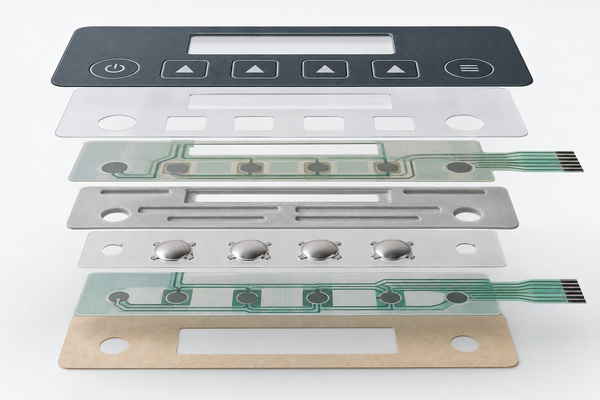
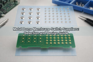
Key centers in the artwork must share datums with the PCB contacts and dome carrier. Display windows must align with the LCD or LED area. Adhesive must be removed where it would interfere with a key cavity, vent path or optical window. When the interface uses a custom dome array, we coordinate array registration with the overlay drawing instead of treating the two parts as independent purchases.
Which Graphic Overlay Materials Should You Choose?
The main graphic overlay materials are polyester (PET) and polycarbonate (PC). Our design guide treats clear film up to 0.25 mm as the normal overlay range; a thicker rigid part behaves more like a plate or nameplate and is less suitable for forming conventional raised keys. The exact grade and thickness still depend on the product environment and forming requirement.
| Decision factor | Polyester (PET) | Polycarbonate (PC) |
|---|---|---|
| Repeated flexing | Often selected for demanding switch areas | Suitable when the chosen grade and key geometry pass the life target |
| Chemical exposure | Common choice where cleaners or oils are important | Verify ink, hard coat and chemical compatibility as a system |
| Forming and fabrication | Requires a controlled forming process | Easy to print, cut and form for many indoor interfaces |
| Optical appearance | Available in clear and textured constructions | Frequently chosen for clear windows and varied finishes |
| Specification rule | Select a named film grade, thickness and surface finish; do not approve only the generic polymer name | |
A polycarbonate graphic overlay is not automatically the economical answer, and PET is not automatically the durable answer. Abrasion coating, solvent exposure, UV, bend radius, embossed-key geometry and the test method can change the result. We therefore tie the material callout to the actual operating conditions.
Why Is Reverse-Side Printing Important?
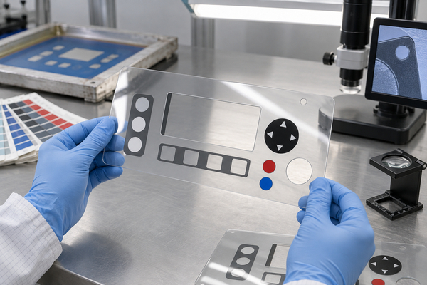
Reverse-side, or subsurface, printing places the ink on the back of a transparent film. Users see the graphics through the material while the front surface remains continuous. This protects legends from direct abrasion and lets a matte, gloss or textured surface be selected independently from the printed colors beneath it.
Color order must be planned in reverse. Transparent windows need clean boundaries, opaque background layers need sufficient coverage, and registration must hold across every print pass. If an icon is intended to remain hidden until illuminated, the dead-front layers and light-transmission target must be defined before artwork release.
Screen Printing or Digital Printing?
Custom graphic overlay printing normally uses screen printing, digital printing or a planned combination. The correct route depends on color construction, artwork complexity, opacity, quantity and revision risk rather than a universal quality ranking.
| Method | Best fit | Engineering checkpoint |
|---|---|---|
| Screen printing | Solid spot colors, opaque layers and repeat production | Mesh, ink system, cure and multi-pass registration |
| Digital printing | Detailed images, gradients, prototypes and shorter runs | Color consistency, opacity and compatibility with film and adhesive |
| Hybrid construction | Graphic detail plus selective opaque or functional layers | Combined registration and cure sequence |
When screen printing graphic overlays, we review each color as a manufacturing layer rather than as a monitor preview. Digital artwork still requires physical color approval because film tint, texture, backing color and lighting change the perceived result. A signed sample or agreed color tolerance is more useful than an unsupported promise of an exact screen match.
How Do Embossing and Metal Domes Work Together?
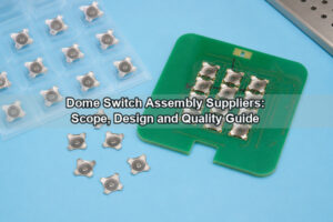
Embossing can create a raised rim, pillow or formed key area in the overlay. It helps users locate a control and provides clearance above the switching element. The emboss does not replace the metal dome; the dome supplies the principal snap and electrical contact, while the overlay shapes the touch surface and transfers force.
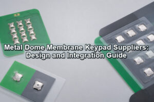
The overlay key center, dome center and PCB contact center must align. Off-center loading can change the feel, reduce margin against edge loading and create uneven cosmetic wear. Key diameter, emboss height, actuator diameter, spacer thickness and allowed over-travel should therefore be reviewed together.
For assemblies that need additional retention between a flexible interface and the circuit, a rubber-glue metal dome array can be evaluated. The array construction must still be selected from the specific surface, force path and environmental seal; the link is a product option, not a substitute for stack validation.
How Should Windows and Backlighting Be Designed?
Display windows can be fully clear, tinted, diffused, textured or dead-front. Their printed boundary must match the active viewing area and enclosure opening. Adhesive and opaque ink should be cut back far enough to avoid visible edges, but not so far that the seal or cosmetic border becomes weak.
A backlit graphic overlay also needs a controlled light path. LED position, diffuser, icon opacity, ambient contrast and leakage between adjacent symbols all affect readability. For a thin multi-key interface, an LGF dome array can combine a light-guide-film route with registered metal domes. We assess the lighting stack together with dome height and key geometry so that illumination does not compromise tactile loading.
How Do You Select the Adhesive?
Adhesive selection starts with the mounting surface, not the overlay alone. Smooth metal, painted metal, powder-coated housings and low-surface-energy plastics require different adhesion strategies. Temperature, moisture, cleaning agents, edge exposure and required removability must also be stated.
When no special condition dictates otherwise, our graphic-overlay designs commonly use adhesive in the 0.05–0.15 mm range. That is a starting range, not an automatic specification. Texture compensation, gasket function, window clarity and step height may require another construction.
- Keep adhesive out of active key cavities, optical windows and required vent channels.
- Use the real housing finish for adhesion trials; a laboratory metal coupon may not represent a coated production enclosure.
- Define liner split, pull tab and assembly datum when operators must position a large overlay accurately.
- Confirm that the adhesive carrier does not interfere with the dome-retainer adhesive or circuit tail.
What Durability Inputs Belong in the Specification?
Durability cannot be reduced to one material name or one actuation number. The specification should describe what the finished interface will experience and how acceptance will be measured. That lets us choose the film, print stack, coating, adhesive and tactile construction against the same target.
- Indoor, outdoor or controlled-environment use, including UV exposure.
- Operating and storage temperature range, thermal cycling and condensation.
- Cleaning agents, oils, hand creams or process chemicals that can reach the surface or edges.
- Abrasion source, cleaning frequency and required legend retention.
- Expected key-use profile, actuation force range and acceptable tactile change.
- Ingress path, enclosure sealing strategy and whether EMI control is required.
When shielding or grounding is part of the interface, we can review an EMI metal dome array together with the overlay and circuit stack. EMI features must have a defined electrical connection and mechanical contact plan; conductive printing alone does not guarantee system-level performance.
What Files and Tolerances Are Needed for a Quote?
Graphic overlays manufacturers can evaluate production requirements more accurately when the input package describes the assembled interface, not only a flattened image. Send vector artwork and a dimensioned mechanical drawing referenced to the same datums used by the enclosure, circuit and dome array.
- Finished outline, corner radii, holes, slots, tail exit and critical dimensions.
- Key centers, emboss type, emboss direction and permitted height range.
- Transparent, tinted, diffused and dead-front window definitions.
- Film grade, thickness, texture, color references and approved viewing light.
- Adhesive coverage drawing, liner requirements and target mounting surface.
- Dome type, actuation force, PCB pad drawing and any lighting or shielding layers.
- Quantity, prototype quantity, inspection level and required environmental tests.
If a tolerance affects artwork-to-contact registration, mark it as critical and show the datum chain. Overly tight general tolerances add cost without protecting function; missing key-center tolerances create a real switching risk.
How Should a Graphic Overlay Prototype Be Verified?
A graphic overlay prototype should be checked on the actual enclosure and circuit whenever possible. A flat sample can approve color and print quality, but it cannot fully prove key feel, edge adhesion, window alignment or assembly handling.
- Compare the physical sample under the agreed lighting condition.
- Check outline, holes, windows, emboss centers and adhesive cutouts against datums.
- Assemble the overlay and press every key across the intended force and travel range.
- Inspect legends, pinholes, color boundaries, window haze and light leakage.
- Run the required cleaning, temperature, humidity and adhesion checks on production-equivalent materials.
For early tactile evaluation on separated controls, a single-key dome array can help confirm dome feel and loading before the full registered array is released. It does not replace final assembly testing, but it can isolate a force-path decision quickly.
Why Source the Overlay, Membrane Switch and Dome Array Together?
Separate suppliers can each make a conforming part while the assembled interface still misses its target. The graphic overlay manufacturing drawing, adhesive pattern, spacer, circuit, metal dome, LED and housing all share key centers and stack height. Coordinating them through one engineering review reduces datum conflicts and makes prototype findings easier to convert into controlled revisions.
We support custom graphic overlays, membrane-switch layers, metal domes and dome arrays as connected parts of the user interface. Our review focuses on material selection, reverse printing, embossing, windows, adhesive coverage, tactile loading, lighting and assembly inspection. That is more useful than choosing each part from a catalog without a common stack drawing.
To request a review, send your artwork, mechanical drawing, circuit or PCB contact layout, target force, environment, lighting requirements and expected quantity to sales@metal-domes.com or use our custom interface quotation form. We will identify the inputs that must be confirmed before a custom graphic overlays design moves from artwork to a production-ready membrane-switch assembly.