An industrial membrane keypad is a sealed, low-profile operator interface whose overlay, tactile elements, circuit, adhesive and mounting structure are specified for the machine’s actual operating conditions. Reliability does not come from calling a keypad “industrial.” It comes from converting water, dust, chemicals, gloves, cleaning, temperature, vibration and duty-cycle requirements into a controlled stack-up and a relevant validation plan.
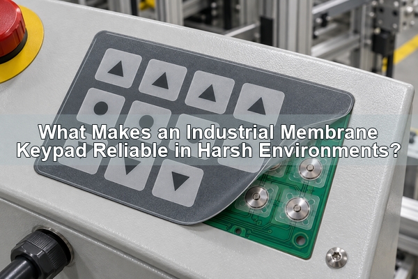
This guide is written for engineers and buyers who must release an interface for industrial controls, process equipment, test systems or machinery. It focuses on the design decisions that affect field performance and on the information a keypad and dome-array manufacturer needs before quoting.

What Makes an Industrial Membrane Keypad Different?
A standard membrane keypad and an industrial membrane keypad can share the same basic layers, but their design inputs are different. The industrial version must remain readable, sealed, electrically stable and comfortable to operate after exposure to the conditions of a real machine. Those conditions may include oily gloves, repeated cleaning, fine dust, condensation, vibration, UV light, electrical noise or a high number of daily actuations.
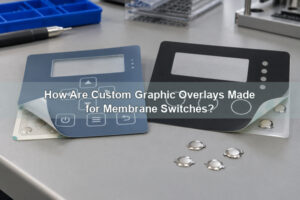
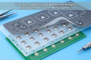
The assembly normally combines a reverse-printed graphic overlay, adhesive and spacer layers, a printed circuit or PCB, tactile or non-tactile contacts, a tail and connector, and a rear mounting adhesive or rigid support. A membrane switch becomes a keypad when those electrical contacts are arranged as a user input interface. The engineering task is to make all layers work as one system.
Which Environmental Loads Must Be Defined First?
Begin with measurable exposure instead of broad words such as rugged or waterproof. A useful environmental brief identifies where the equipment operates, what reaches the front panel, how often it is cleaned and what the operator wears. The enclosure and keypad must then be evaluated together; a sealed overlay cannot compensate for an unsealed tail exit or enclosure joint.
| Operating input | Design question | Typical keypad consequence |
|---|---|---|
| Water, spray or washdown | Direction, pressure, duration and cleaning method? | Perimeter gasket, sealed window, tail-exit detail and system-level ingress test |
| Oil, coolant or detergent | Exact chemical and contact time? | Overlay, ink and adhesive compatibility review |
| Dust and particles | Particle size and accumulation path? | Closed front surface, edge sealing and enclosure interface control |
| Temperature and humidity | Operating, storage and cycling range? | Material expansion, adhesive behavior and condensation review |
| Gloved operation | Glove type and required confirmation? | Larger key zones, stronger tactile response and clearer embossing |
| Daily key cycles | Which keys carry the highest duty? | Dome selection, force target and life-cycle validation by key |
An IP target is a requirement for the completed product under a defined test, not a property that can be assigned to one loose layer. Specify the desired rating and test configuration, then confirm how the keypad, enclosure, gasket, cable entry and connector will be assembled.
How Should the Overlay Withstand Chemicals and Abrasion?
The graphic overlay is the user’s contact surface, so its material and print system must match the exposure. Polyester is often considered where flex endurance and chemical resistance matter. Polycarbonate can be useful for graphic clarity and forming, but its suitability still depends on the cleaner, coating and abrasion requirement. A material name alone is not an approval.
Reverse printing places graphics behind the transparent surface and protects legends from direct rubbing. Hard coats, textures and selective clear windows can be specified where needed. Test coupons should use the production-intent film, ink and coating, because the same cleaner can affect an uncoated window differently from a textured printed area.
Key legends must remain legible under factory lighting and with the viewing distance of the real operator. Embossing or finger guides can help locate keys, but height, edge radius and overlay thickness must still allow the selected tactile element to collapse correctly.
Which Tactile Architecture Fits the Operator and Duty Cycle?
Industrial membrane switches can use metal domes, formed polyester domes or flat non-tactile contacts. The choice should follow the required feedback, force window, profile, circuit construction and expected use rather than a universal preference.
| Architecture | Best fit | Engineering watchpoint |
|---|---|---|
| Metal dome array | Distinct tactile snap and repeatable key location | Pad geometry, dome alignment, venting and actuator centering |
| Polydome | Integrated flexible construction and lighter tactile designs | Formed profile, printed conductor and stack-up control |
| Flat contact | Lowest profile where audible or tactile snap is not required | Operator confirmation and accidental actuation |
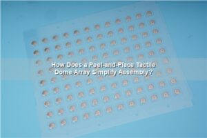
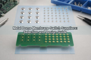
Our polydome versus metal dome array comparison helps separate these choices. When a metal dome is selected, a registered custom dome array can place different dome sizes, shapes or forces on one PET carrier according to the key layout.
How Do Actuator Geometry, Force and Travel Work Together?
The force felt at the overlay is not determined by the dome alone. The key diameter, emboss height, overlay stiffness, spacer opening, actuator diameter, actuator height and alignment all change how load reaches the dome. An off-center or undersized actuator can produce uneven loading, weak feedback or local wear even when the dome specification is correct.
Where the overlay or rubber key cannot press the dome directly, a plunger dome array creates a controlled force path. We can evaluate plunger diameter, height and total assembly height against the chosen dome and the available stack. EBest Circuit(Best Technology) publishes plunger diameters of about 0.8–3.2 mm and adjustable plunger height of about 0.1–0.40 mm; the final combination still requires project-specific review.
How Should Sealing and Venting Be Balanced?
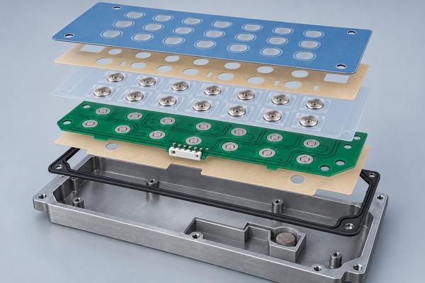
Sealing keeps contamination away from the electrical contacts, while venting allows trapped air around a tactile dome to move during actuation. Blocking every air path can make keys feel slow or inconsistent. Opening a vent directly to the exterior can create an ingress route. The solution is a controlled internal air path that remains inside the sealed boundary.
Perimeter adhesive width, cutout spacing, tail exit, connector location and display windows all need separate review. A rubber-glue metal dome array can provide a compliant bonding interface to a keypad or PCB structure, but it does not replace the enclosure-level seal. Adhesive selection must consider surface energy, temperature, chemical exposure and assembly pressure.
What Circuit, Tail, Connector and ESD Details Matter?
The circuit drawing should define the key matrix, common lines, pinout, tail length, tail bend area, pitch, connector orientation and any components integrated into the interface. The tail must reach the mating connector without a sharp fold or continuous tensile load. Keep stiffeners and connector hardware outside the active bend zone.
Industrial controls may also need a defined ESD or EMI path. Shielding is only useful when its termination and chassis relationship are known. Our EMI metal dome array can add silver or silver-carbon printing to an array structure for an engineered ESD path. Grounding location, contact method and acceptance test must be stated in the drawing rather than assumed.
How Should Backlighting and Display Windows Be Integrated?
Backlighting is a system of LEDs, optical layers, printed masks, key legends and mechanical clearances. It should be reviewed for uniformity at the minimum and maximum operating brightness, not only photographed in a dark room. Light leakage between adjacent keys and bright spots near LEDs are common signs that the optical stack needs adjustment.
For a low-profile design, an LGF dome array combines a light guide film with the dome-array stack. We publish an LGF thickness of about 0.125 mm and can adjust printed or die-cut patterns for the target key layout. The required color, LED position, brightness tolerance and viewing environment belong in the specification.
Display windows need their own requirements for clarity, tint, texture, scratch resistance and sealing. Avoid routing adhesive or printed opaque ink into the visible area, and confirm the finished window against the actual display rather than a blank color sample.
What Mounting and Enclosure Details Prevent Field Failures?

A keypad can pass bench testing and still fail after installation if the mounting surface is uneven, contaminated or too flexible. The drawing should specify the panel cutout, flatness, corner radii, edge distance, fasteners, cable clearance and the sequence used to laminate the keypad to the enclosure.
The support behind each key must prevent local panel flex from absorbing actuation force. Cable glands, emergency stops and enclosure seams should not distort the keypad area. For wet cleaning, place edges, windows and tail exits so water cannot remain against the adhesive boundary.
Gloved use also changes human factors. Key zones may need more area and spacing, while critical functions may need shape, color or force differentiation. These choices should be verified with the real gloves and operator posture instead of relying only on a drawing.
Which Prototype Tests Should Represent the Real Machine?
A useful prototype proves the production-intent stack, not just artwork. Test the complete keypad on a representative enclosure with the intended connector and firmware. Acceptance criteria should cover electrical operation, tactile force, visual quality, assembly and the environmental risks identified at the start.
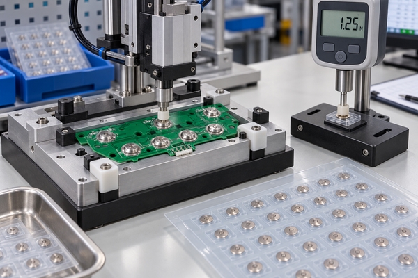
- Measure trip force and return response across representative keys, including corners and high-duty keys.
- Cycle the most frequently used keys for the required life target, then recheck force and contact behavior.
- Expose production-intent overlay coupons to the stated cleaner, oil or coolant and inspect print, coating and adhesive.
- Run temperature or humidity conditioning when material expansion, condensation or adhesive performance is a risk.
- Perform the required ingress test on the assembled enclosure, including windows, tail exit and cable entry.
- Check ESD behavior using the defined shielding and grounding configuration.
- Verify readability, backlight uniformity and gloved operation under the machine’s actual lighting.
EBest Circuit(Best Technology) provides trip-force measurement, rebound-force measurement and life-cycle test support for metal domes and dome arrays. Our published dome-array capability includes force tolerance of approximately ±25 gf and life above 1,000,000 cycles for applicable structures; these are capability references, not automatic acceptance limits for every completed keypad.
When Should a Membrane Keypad Be Replaced or Redesigned?
A membrane keypad replacement should preserve the electrical and mechanical interface only when the original design is still suitable for the environment. If legends wear early, edges lift, keys lose snap, water reaches contacts or operators miss inputs with gloves, duplicating the old construction can reproduce the same failure.
For replacement work, provide the original drawing if available, a flat sample, connector and pinout details, enclosure dimensions, failure photos and the actual cleaning or exposure history. A redesign may change the overlay material, adhesive boundary, dome force, actuator geometry, circuit tail or mounting surface while preserving the equipment’s electrical interface.
What Should You Include in an Industrial Keypad RFQ?
A complete RFQ allows us to separate mandatory requirements from preferences and identify conflicts before tooling or samples. Send the following information:
- 2D drawing, CAD, Gerber, PDF or a dimensioned sample showing the key layout and outline.
- Application, enclosure material, mounting surface and available stack height.
- Operating and storage temperature, humidity, water, dust, UV and chemical exposure.
- Overlay material, finish, colors, legends, embossing, windows and backlighting requirements.
- Tactile preference, target force, travel, sound and glove type.
- Circuit schematic or matrix, tail length, pinout, connector and shielding requirements.
- Required life cycles, validation standard and acceptance criteria.
- Prototype quantity, annual volume and production schedule.
We manufacture metal domes, polydomes and multiple dome-array structures for keypad interfaces, and we can review CAD, PDF, Gerber, PCB/CAM files or customer drawings. Share the operating environment before requesting a price so our recommendation reflects the real machine rather than a generic layer stack.
How Can EBest Circuit Support Your Industrial Keypad Project?
At EBest Circuit(Best Technology), we have manufactured metal domes and metal dome arrays since 2006. We support single-layer, double-layer, EMI-printed, rubber-glue, LGF, plunger and custom array configurations, including prototypes, low-volume builds and scalable production. Our engineering review connects dome geometry, carrier layout, force path, venting and assembly requirements to the keypad drawing.
For an industrial membrane keypad project, send your layout, environment, tactile target, circuit data and forecast to request a manufacturing review and quotation. We will identify the inputs that still need confirmation before samples are released.