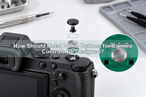
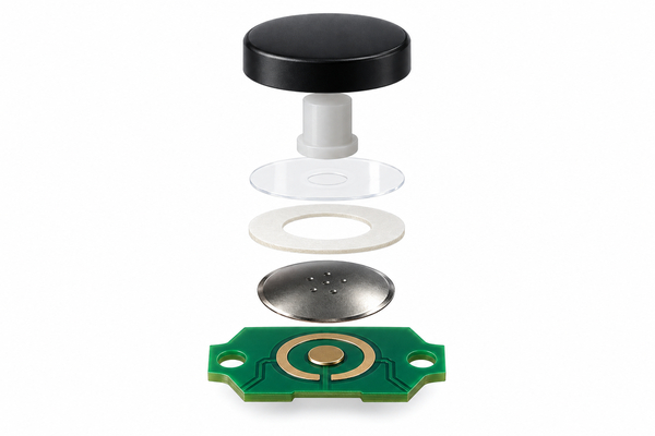
Metal dome buttons for camera controls are internal snap-action contacts used beneath a keycap or actuator to create a momentary electrical signal and a clear tactile response. They are different from the decorative metal shutter release button or metal shutter button that screws onto the outside of some cameras. For an internal camera button switch, reliable feel depends on the complete stack: keycap, plunger, carrier, dome, PCB or FPC contacts, venting and housing travel stop.
What Are Metal Dome Buttons for Camera Controls?
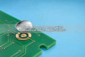
A camera metal dome button is a normally open, momentary contact built around a thin formed spring-metal dome. When the actuator reaches the trip point, the dome snaps downward and connects the center PCB contact to the outer contact. Removing the load allows the dome to recover and reopen the circuit.

A dome switch button in this context is also called a tactile dome switch or metal dome switch. Those names describe the internal electrical contact, not the visible camera cap.
This article covers internal tactile dome switch construction. An external soft-release accessory may also be called a camera shutter button, but it is only a cap or extension for a mechanical threaded socket. It does not replace the internal electrical switch. That distinction matters when specifying parts, diagnosing feel or preparing design requirements.
Which Camera Buttons Can Use a Metal Dome?
Metal domes can be considered for compact camera buttons that need low profile, momentary operation and positive tactile confirmation. Typical positions include menu, playback, record, function, directional and confirmation keys. A shutter release button may also use a tactile contact, but its electrical sequence must match the focus and exposure functions of the camera.
Camera shutter buttons deserve separate evaluation because a shutter button for camera equipment may need two controlled electrical events rather than one simple on-off contact.
Not every control should use the same dome. A frequently used camera shutter button may require a different force, travel and housing guide from a small menu key. Rotary dials, sliding switches and controls that must remain latched need different mechanisms.
How Does the Snap Dome Create Tactile Feedback?
The tactile event comes from elastic instability in the curved dome. Force rises as the actuator deflects the dome, drops when the dome snaps through and rises again if the user continues to press against the housing stop. The return event occurs as the dome recovers after the load is removed.
The user does not feel the loose dome alone. Keycap mass, plunger diameter, preload, overlay stiffness, adhesive thickness, support flatness and over-travel all alter the final response. A finger test on a loose tactile dome switch therefore cannot approve the production camera assembly.
How Should a Two-Stage Camera Shutter Button Be Handled?
A conventional metal dome normally provides one electrical make-and-break event. A two-stage shutter button needs two distinct signals: the first stage commonly initiates focus or metering, while the second stage releases the shutter. One ordinary dome should not be described as creating both stages by itself.
Two-stage operation requires a dedicated mechanical and electrical architecture, such as a purpose-designed two-stage switch or two independently defined contact events with controlled sequencing. The first-stage force, second-stage force, travel separation and debounce behavior must be verified in the complete camera shutter switch. Simply placing two contacts beneath one key does not guarantee a repeatable half-press and full-press.
Which Dome Shape and Size Fit Camera Controls?
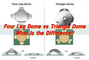
A round metal dome is often practical for a circular camera key because it does not require rotational orientation and can fit a compact envelope. Shape selection still depends on the available area, actuator guide, contact geometry, force target and placement process. Four-leg, triangle or oblong domes should not be substituted merely because their outline looks similar.
Size must be selected from the actual mechanical stack. A smaller dome can save space, but it also reduces the available actuator target and makes offset loading more critical. The approved dome drawing, not a generic camera-button diameter, should control the PCB footprint and housing clearance.
The label mini metal dome is not a dimensional specification. State the required diameter, height, force and travel instead of relying on a broad size description.
How Should the Keycap and Plunger Contact the Dome?
The actuator should load the center of the dome with a primarily vertical force. A guided plunger helps transfer force from the external keycap while limiting side load. Its diameter and end shape must suit the selected dome without contacting the unsupported edge or pushing through an unintended opening.
Housing ribs should guide the button without binding, and a positive stop should limit over-travel after electrical closure. Excessive preload can make the key feel heavy or partly collapsed; excessive free play can create rattle, delayed response and uneven feel between adjacent camera buttons.
How Should PCB and FPC Contact Pads Be Designed?
The circuit normally uses an electrically isolated center contact and an outer contact that supports the dome perimeter. The dome bridges those two nodes only after snap-through. Keep solder, raised mask, vias, debris and surface damage out of the active support and contact areas.
- Match the center pad, outer contact and dome support region to the approved component drawing.
- Use PCB or FPC datums that also control carrier and housing alignment.
- Keep the contact surface flat, clean and compatible with the required environment.
- Provide a controlled vent path without routing contamination toward the contact area.
- Review flex-circuit bending and stiffener support so the contact area does not deflect under actuation.
Which Force, Travel and Click Ratio Should Be Specified?
There is no universal force target for metal dome buttons for camera controls. The correct value depends on key area, finger use, gloves, accidental-press risk, actuator leverage and the required difference between neighboring controls. A video-record key may intentionally feel different from a directional key, while a shutter control needs a clearly defined sequence.
| Specification | What it controls | What to verify in the camera |
|---|---|---|
| Trip force | Load at snap-through | Intended press versus accidental activation |
| Return force | Recovery margin | Reliable release after the keycap load is removed |
| Travel | Movement to and through actuation | Housing clearance and stop position |
| Click ratio | Sharpness of tactile drop | Perceived confirmation through the full stack |
| Height and tolerance | Stack position | Preload, free play and key-to-key consistency |
Approve these values on production-intent samples. The dome specification and the finished-button acceptance limits should be related, but they are not automatically identical because the housing, adhesive and actuator add their own variation.
How Do Dust, Moisture and Venting Affect the Button?
Camera controls may encounter dust, humidity, skin oils and outdoor temperature changes. A protective carrier and perimeter adhesive can help isolate the contact, but the dome cavity still needs controlled air movement as the dome collapses and returns. A completely trapped cavity can slow recovery or change feel.
Place vents where adhesive cannot block them and where they do not become a direct contamination path. Sealing performance belongs to the complete enclosure, overlay, carrier, adhesive, vent and circuit design. A metal dome alone does not provide an environmental rating.
Should You Use Loose Domes, Single-Key Arrays or a Custom Array?
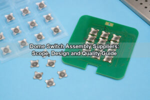
The supply format should follow the camera layout, placement process and service strategy. A loose dome can work for controlled prototype or automated placement. A single-key dome array provides an individual peel-and-place carrier, while a custom dome array locates multiple camera controls on one registered sheet.
| Format | Best fit | Main control point |
|---|---|---|
| Loose dome | Prototype or dedicated placement process | Orientation, cleanliness and individual positioning |
| Single-key array | Separate button locations or serviceable modules | Peel-and-place datum and local venting |
| Custom array | Rear key clusters and repeated production | Carrier registration, adhesive openings and mixed key requirements |
| Plunger array | Stack needs added actuator height | Plunger diameter, height and center alignment |
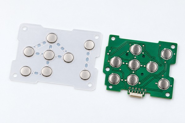
When the keycap needs a defined transfer point, a plunger actuator dome array can integrate the actuator with the carrier. Feasibility still depends on the final stack height, key geometry and force target.
Which Camera Button Failures Should Prototypes Catch?
Prototype testing should expose failures caused by the complete assembly, not only obvious electrical opens. Common risks include an off-center actuator, carrier shift, uneven PCB support, adhesive intrusion, trapped contamination, insufficient return margin and excessive housing over-travel.
- A button that works only when pressed on one edge indicates alignment or guidance risk.
- A weak or inconsistent click may result from preload, stack tolerance or local flexing.
- Intermittent closure can come from contamination, contact finish, pad geometry or dome damage.
- Slow return after environmental exposure can indicate venting or adhesive interaction.
- Different feel among adjacent camera buttons can reveal mixed stack heights or support conditions.
How Should Camera Button Performance Be Tested?
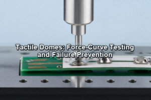
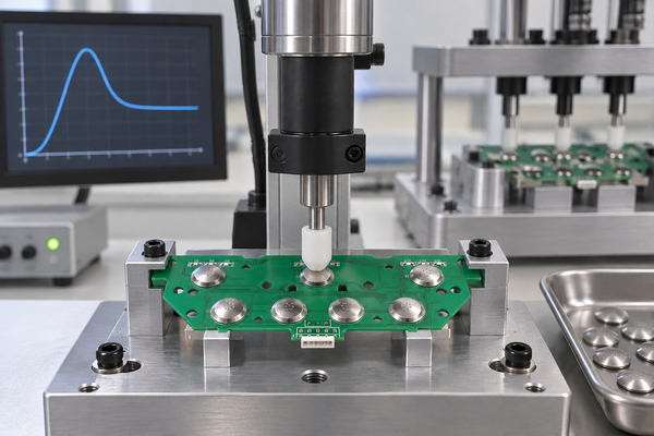
Use a centered force probe and the production-intent actuator to measure the force-displacement response while the circuit records electrical closure and release. Check trip force, return force, travel, contact timing and key-to-key consistency. For a two-stage shutter button, record both electrical events and the mechanical separation between them.
Life testing should use the intended press point, rate, over-travel limit and environment. Inspect the dome, carrier, adhesive, contacts and housing after cycling. EBest Circuit(Best Technology) can perform trip-force, rebound-force and life-cycle evaluation for metal dome and dome-array projects; the acceptance plan remains subject to the selected structure and customer requirements.
What Manufacturing Inputs Control Consistency?
Consistency starts with one controlled stack definition. The released drawing should connect dome geometry and force to the PCB/FPC pads, actuator, carrier, adhesive, vent and housing stop. Changing one layer without reviewing the others can move the button away from its approved tactile window.
We have manufactured metal domes and metal dome arrays since 2006. For custom camera controls, we can review trip force, return force, click ratio, travel and height, and we can develop array layouts from CAD, PDF, Gerber, PCB/CAM files or customer drawings. These capabilities support engineering evaluation; final values depend on the selected dome series and complete camera assembly.
What Design Inputs Should You Send for Engineering Review?
Send the button layout, PCB or FPC contact drawing, available diameter and height, actuator dimensions, target force and travel, key functions, sealing and venting requirements, expected life, environmental conditions, packaging format and annual quantity. For a shutter button on a camera, identify whether the requirement is single-stage or half-press/full-press and provide the required electrical sequence.
EBest Circuit(Best Technology) can compare a standard round part with a custom metal dome or array solution and review the complete interface before confirming a design path. Send the drawing and stack details to sales@metal-domes.com.
Use the same approved files for prototype and production review. That keeps the metal dome buttons for camera controls tied to the intended contact geometry, tactile target and assembly process instead of a generic replacement part.