A standalone dome switch is one metal snap dome installed over a dedicated PCB or FPC contact pattern rather than supplied as part of a multi-key carrier. It is useful when a design has one key, widely separated keys, prototype quantities or an assembly process that can control each dome individually. The choice also transfers retention, alignment, venting and cleanliness responsibilities to the product designer and assembler.
What Is a Standalone Dome Switch?
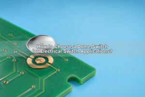
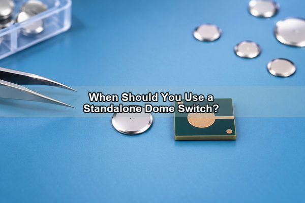
A standalone dome switch is the switching element for one key. The shallow formed metal dome provides both spring action and the moving electrical contact. Its perimeter rests on the outer pad, while its crown moves toward the center pad when pressed. A circle metal dome is a common compact format for this type of single-key construction.
The terms single dome switch, tactile dome switch and metal dome switch are often used around the same product family, but they do not always describe the same delivery format. In this article, standalone means a loose or individually retained metal dome, not a complete packaged tact switch and not a sheet that locates several domes.
If the question is “What is a dome switch?” the short answer is a momentary contact created by a collapsible dome over a circuit. “What is a tactile dome switch?” adds the requirement that the snap action gives the user a detectable force change. Neither phrase alone tells the assembler how the dome is positioned.
How Does a Standalone Dome Switch Work?
At rest, the dome perimeter touches or rests on the outer conductive region while the center contact remains open. A centered actuator loads the crown. At the trip point, the metal shape snaps through and reaches the center pad, closing the circuit. When the load is removed, stored elastic energy returns the dome and opens the contact again.
This directly answers “How does a dome switch work?” but a reliable snap dome switch also depends on its surrounding structure. Pad height, circuit flatness, actuator diameter, preload and trapped air can all change the force curve or prevent complete return. The dome is a critical component, not the whole switch assembly.
How Is It Different from a Dome Array or SMD Dome Switch?
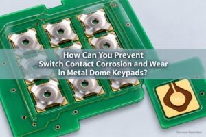
The three formats can use a similar snap action, but they assign assembly responsibilities differently. A loose metal dome leaves individual placement and retention to the assembler. A dome switch array holds one or more domes at controlled coordinates under a carrier. An SMD dome switch is configured for solderable automated placement and should not be treated as a loose part.
| Format | Best fit | Main integration responsibility |
|---|---|---|
| Standalone loose dome | One key, spaced keys, prototype or controlled manual assembly | Customer controls retention, location, venting and cleanliness |
| Single-key adhesive carrier | One key that needs easier handling and defined local retention | Carrier outline and adhesive interface must match the board and housing |
| Metal dome array | Several keys with shared registration and lamination | Array drawing controls dome coordinates, adhesive windows and vent paths |
| SMD dome switch | Automated solderable assembly | PCB land pattern, reflow process and package handling govern placement |
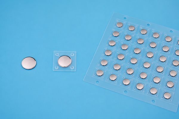
A membrane dome switch can contain a metal dome beneath a graphic or carrier membrane, so “membrane” and “metal dome” are not always competing technologies. This is also different from how rubber dome switches work: a rubber web supplies the spring behavior and may use a conductive pill, while a metal snap dome is a separate formed contact. For multi-key registration, a custom metal dome array can reduce individual placement work.
When Is a Standalone Dome Switch the Better Choice?
A standalone dome switch is usually the better choice when the product has only one tactile key, when the keys are far apart, or when the housing already contains reliable pockets that locate each dome. It can also suit prototype builds where engineers need to compare dome shapes or force options without ordering a complete carrier tool.
- Use it for a single power, reset, pairing or service key with a defined local cavity.
- Use it when widely separated keys make a full-size carrier inefficient.
- Use it when the assembly fixture can control position and contamination.
- Use it for early tactile evaluation before the final array outline is frozen.
It is a weaker choice when many closely spaced keys must align in one operation, when manual placement cost dominates, or when a sealed laminated keypad needs shared adhesive and vent channels. In those cases, a metal dome array or solderable SMD format may provide a clearer manufacturing path.
Which Metal Dome Shape Fits a Standalone Key?
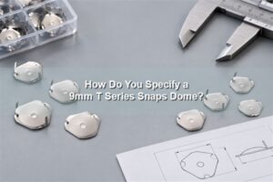
Shape selection begins with the available footprint, pad topology, actuator, desired force curve and vent route. Circular switch domes use space efficiently and suit centered loads. Four-leg metal domes provide defined support points and open regions between the legs, which can help the designer coordinate traces and airflow.
Triangle metal domes can fit constrained geometries or a pad layout designed for three support regions. Oblong domes can serve narrow rectangular keys. These shapes are not drop-in substitutes: changing the outline changes the PCB contact pattern, support condition and actuator relationship.

Do not choose a snap dome from diameter and nominal force alone. Confirm the actual drawing, center-hole or dimple condition, height, travel, return behavior, plating requirement and tolerance. A center-hole design also needs a compatible contact concept; it must not be placed over a center pad as though the hole were conductive material.
How Should You Design the PCB Contact Pad and Vent Path?
The center contact must remain electrically isolated from the outer support contact until actuation. The outer region should support the selected dome evenly without solder-mask ridges, exposed vias or irregular plating under its seating area. The printed circuit board or flex circuit also needs sufficient local support so the pad does not deflect and absorb dome travel.
Every press changes the air volume beneath the dome. Provide a controlled vent route through a spacer opening, a gap between support legs or another defined channel. A blocked cavity can slow reset or alter feel; an uncontrolled path can carry debris or moisture toward the contact. Our PCB contact pad design guide covers the pad, clearance and venting checks that should accompany the dome drawing.
How Can You Hold and Position a Loose Dome?
A loose dome must remain centered before the enclosure is closed and throughout product use. A molded pocket can provide lateral control, but it must not pinch the dome edge or block venting. Small adhesive features or a die-cut spacer can retain the part, provided adhesive cannot creep beneath the contact area.
A single-key peel-and-place carrier is useful when the project still needs one independent key but wants easier handling. Its carrier window, adhesive thickness, release liner and placement datum must be defined. The transparent sheet should hold the dome without preloading its crown.
Whichever method is used, document the location tolerance relative to the PCB pad and actuator. Manual placement without a datum may be acceptable for an early sample, but it is not a production control plan. Clean handling, covered storage and an assembly fixture reduce fingerprints, particles and dome inversion.
How Do the Actuator and Stack-Up Change Tactile Feel?
The actuator should apply force near the dome center and remain centered as the visible key moves. An off-axis or oversized plunger can tilt the dome, load a support leg first or rub the retention layer. A very small contact tip may create a sharp local load instead of the intended distributed press.
Finished key feel also depends on keycap leverage, overlay stiffness, carrier thickness, air gap and circuit support. Excess preload can reduce travel or leave the dome partly collapsed. Too much clearance can make the key feel loose before the snap event. Hard stops are useful when the user can continue pressing after electrical contact.
Evaluate the actual stack rather than approving the component force in isolation. Two metal dome switches with the same nominal trip force can feel different when their actuator diameter, support stiffness or travel allowance changes.
What Should You Test Before Production?
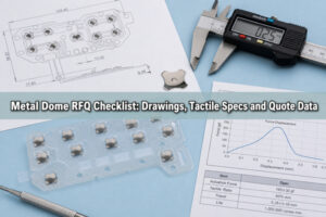
Testing should separate loose-component checks from assembly-level checks. First confirm dome outline, surface condition, dimensions and force-displacement behavior. Then build the production-representative PCB, retention method, actuator and housing so the team can measure the finished key.
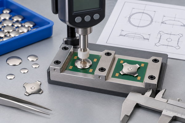
- Measure trip force, return force and travel with the intended actuator.
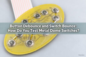
- Verify electrical closure, contact resistance method and bounce criteria.
- Test center and edge presses on the visible key.
- Inspect retention, dome position, adhesive intrusion and vent continuity.
- Run the environmental and cycle plan required by the actual product.
Do not convert a supplier example into a universal life claim. Cycle count, temperature, contamination and acceptance limits depend on the selected dome, circuit, assembly and end-use requirement.
How Do We Support a Standalone Dome Switch Project?
At EBest Circuit(Best Technology), we manufacture loose metal domes and related carrier assemblies for PCB and FPC interfaces. We review the customer drawing for dome outline, force, travel, center condition, surface requirement, pad compatibility, actuator relationship and packaging method. For a nonstandard footprint or tactile target, our custom metal domes provide a project-specific path rather than forcing an unrelated standard part into the design.
Send us the PCB or FPC pad drawing, available cavity, actuator dimensions, target tactile response, retention concept, expected environment and validation requirements. We can then discuss whether a loose dome, a single-key carrier or a full array is the more controllable format. To review a standalone dome switch design, contact our engineering team at sales@metal-domes.com.