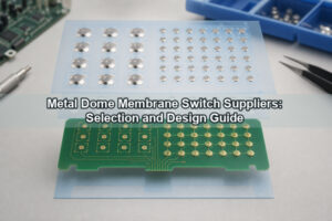
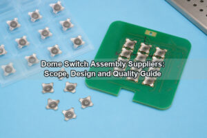
A metal dome RFQ checklist should define the product form, dome geometry, tactile targets, contact-pad layout, array construction, operating conditions, test requirements, quantities and packaging. A complete package lets the manufacturer evaluate fit, tooling, process risk and unit pricing against one controlled revision instead of estimating from an isolated force value or product photo.
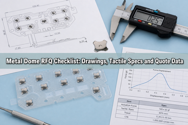
The RFQ does not need every field to be final. It should separate locked requirements from preferred targets and open items. This allows standard parts to be considered where appropriate while identifying specifications that require a custom dome, custom array, sample evaluation or dedicated tooling.
What Should a Metal Dome RFQ Checklist Contain?
The checklist should contain enough mechanical, tactile, electrical and commercial data to identify what is being supplied and how acceptance will be judged. The minimum useful package is a revision-controlled drawing, the intended product form, dome size and force, contact layout, operating environment, prototype quantity and annual usage.
- Project name, drawing number, revision and quotation date.
- Loose metal dome, peel-and-place sheet, custom dome array or solderable SMD dome switch.
- Dome shape, dimensions, height, dimple or center-hole details and material or plating requirements.
- Trip force, release force, travel, tactile ratio and any force tolerances.
- PCB, FPC or membrane contact-pad layout with dome coordinates and datums.
- Carrier, adhesive, spacer, vents, cutouts, actuator and overlay stack information.
- Contact resistance, bounce, mechanical life and environmental test requirements.
- Prototype quantity, annual usage, production lot size and packaging method.
Mark each item as required, preferred or supplier-proposed. For example, a fixed enclosure may lock the diameter and total stack height, while the manufacturer may still recommend the dome series and force tolerance.
Which Product Form Should Be Quoted?
The product form should match the assembly process. Loose domes suit controlled manual or automated placement when the board or keypad already provides retention. A peel-and-place format positions one or more domes on an adhesive carrier. A custom array adds a defined outline, coordinates, cutouts and optional spacer or functional layers. An SMD dome switch is a packaged part intended for SMT assembly.
| Product form | Specify in the RFQ | Best fit |
|---|---|---|
| Loose metal dome | Series, size, force, orientation and bulk/tube packaging | Existing retention structure or dedicated placement process |
| Peel-and-place dome | Dome part number, sheet layout, adhesive and release liner | Prototype, manual installation or grouped placement |
| Custom dome array | Carrier outline, X/Y locations, layers, vents, cutouts and datums | Repeatable multi-key alignment on PCB, FPC or membrane circuit |
| SMD dome switch | Package, footprint, height, force, reflow profile and tape orientation | Automated SMT assembly |
The metal dome array range covers single-layer, double-layer, EMI, rubber-glue, LGF and custom structures. When a reflow-solderable package is required, quote an SMD dome switch rather than treating a standard snap dome as a solderable component.
What Drawing Files and Revision Data Are Required?
The RFQ drawing should establish one geometric source of truth. Include the PCB or FPC contact pattern, carrier outline, dome centers, key pitch, tooling holes, cutouts, keep-outs, orientation features and critical tolerances. Add a section or side view when the array, adhesive, actuator or enclosure controls total height.
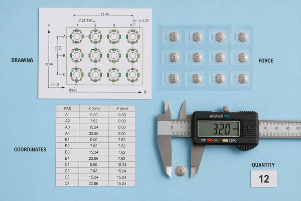
Useful source files include AutoCAD, PDF, Gerber, PCB and CAM data. EBest Circuit(Best Technology) also accepts a hand sketch for an initial engineering review or budgetary quotation, but production release still needs controlled dimensions and revision identification. If several files are supplied, state which file governs dimensions when they disagree.
- Drawing number, revision letter, release date and unit system.
- Top-view orientation and a clearly marked datum origin.
- Dome-center coordinates or a dimensioned pitch pattern.
- Carrier perimeter, corner radii, slots, holes and component clearances.
- General tolerances plus tighter tolerances only on genuinely critical features.
- Exploded stack-up showing layer order, thickness and adhesive side.
Send native data together with a viewable PDF. The PDF preserves revision notes and intended appearance, while native files reduce coordinate transcription during engineering preparation.
Which Dome Shape and Size Specifications Must Be Defined?
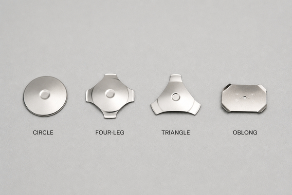
Specify the dome shape, nominal dimensions, free height, edge features and the contact-pad geometry it must bridge. Circle, four-leg, triangle and oblong metal domes transfer force and contact the circuit differently, so a diameter alone does not define an interchangeable part.
For a standard part, provide the manufacturer part number if known. For a custom metal dome, include the plan-view dimensions, leg or corner geometry, center dimple or hole, free height, material or plating, and any restricted orientation. EBest Circuit(Best Technology) publishes a broad standard range, but the final available force and geometry must be confirmed for the selected series and size.
Do not copy only the outside dimension from an existing sample. Measure or specify the active pad arrangement, actuator contact area and permitted dome movement. An actuator that lands near one edge can produce a different force curve and service life from centered actuation even when the metal dome itself is unchanged.
How Should Trip Force, Release Force, Travel and Tactile Ratio Be Specified?
Tactile requirements should be stated as measurable targets with units, tolerance and test condition. Trip force is the peak force at snap-through. Release force is the force during return. Travel is the displacement to electrical closure or snap-through, depending on the test definition. Tactile ratio is commonly calculated from trip and release force, but the exact formula should be stated when it is an acceptance criterion.
- Use `gf` or `N` consistently and include an allowed tolerance.
- Define whether force is measured on the bare dome, in the array or through the completed actuator stack.
- State the probe diameter, actuation point and test speed when the result is sensitive to the method.
- Define minimum return behavior where slow release or key sticking is unacceptable.
- Attach an approved force-displacement curve when matching an existing keypad feel.
A target such as “medium click” is useful only as a preference. Pair it with an approved sample, target force curve or numerical window. The overlay, plunger, adhesive and housing can change the perceived feel, so bare-dome data and finished-keypad acceptance should not be treated as the same measurement.
What PCB or FPC Contact-Pad Information Is Needed?
The contact-pad drawing should show the center contact, outer contact, solder-mask or coverlay openings, trace exits, vias, nearby components and the dome center. Include the surface finish and any cleanliness or residue restrictions because the dome closes the circuit directly across this surface.
Dimension the pad from stable PCB or FPC datums, not from a decorative overlay. State whether the dome rests directly on the circuit, inside a spacer cavity or on a plated contact feature. Keep copper, mask edges and conductor transitions away from areas where the dome rim must move freely.
For flexible circuits, define the support condition under the pad. Local flexing changes travel and tactile response. If the FPC is bonded to a stiffener or housing, include the support thickness, adhesive and opening beneath the key area in the stack-up drawing.
Which Array, Adhesive, Spacer and Venting Details Should Be Included?
A custom array RFQ should define the carrier material, total outline, adhesive type or performance requirement, spacer construction, cavity openings, vent routes, release liner and any printed or conductive layer. These details determine tooling, lamination, handling and whether each dome can move without being preloaded.
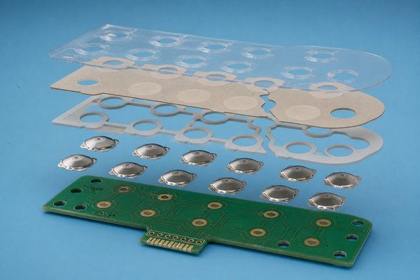
For a custom dome array, provide the carrier size and shape, dome part numbers, dome positions, cutouts and annual usage. A single sheet may combine different dome sizes, shapes and force values when the layout requires it. The drawing should also identify the side from which the release liner is peeled and any tab needed for handling.
Show each vent path instead of adding a general note that the array must breathe. A blocked cavity can trap air, change return behavior or hold the dome above the contact surface. For a double-layer structure, define spacer thickness and the connection between individual key cavities and the vent exit.
What Actuator, Overlay and Stack-Up Dimensions Affect the Quote?
The quotation should account for every layer that transfers force to the dome. Provide actuator or plunger diameter, height, hardness or material, alignment tolerance and the intended contact point on the dome. Add overlay, graphic layer, rubber key, LGF, spacer, adhesive, circuit and support thicknesses to a single stack-up.
Identify minimum and maximum assembly height rather than only nominal values. The tolerance stack can preload the dome or create excess lost motion. If the actuator is off-center, show its worst-case position relative to the dome and request an engineering check of edge loading.
When a raised actuation point is needed, a plunger array may integrate the actuator with the carrier. If the overlay or rubber key already supplies a molded post, quote the dome array without duplicating that feature and provide the post geometry for review.
Which Electrical and Reliability Requirements Must Be Stated?
Electrical and reliability requirements should use measurable limits and a defined sample plan. Relevant fields include contact configuration, maximum switching load, contact resistance, bounce, insulation or breakdown requirements, mechanical life and the conditions under which those values are tested.
| Requirement | RFQ detail to provide | Why it changes the review |
|---|---|---|
| Contact resistance | Maximum initial value and post-life value | May affect surface finish, plating and test method |
| Contact bounce | Maximum time and measurement circuit | Influences electronic filtering and acceptance setup |
| Mechanical life | Cycle target, actuation rate, load and environment | Defines validation time and sample quantity |
| Force consistency | Nominal, tolerance and lot sampling | Controls sorting and inspection requirements |
| ESD or EMI behavior | Applicable standard and stack requirement | May require conductive printing or grounding features |
Published product values are useful for initial selection, but the RFQ should reference the selected part or array construction. Do not apply one series’ resistance, force or life data to a different shape, plating or finished keypad without confirmation.
What Environment, Compliance and Cleaning Conditions Matter?
State the operating and storage temperature, humidity, condensation risk, salt or chemical exposure, dust, vibration and cleaning process. Also list the required material declarations or compliance documents. The relevant condition is the environment at the switch interface, not only the ambient rating of the complete device.
For outdoor, medical, automotive or industrial equipment, identify cleaning agents, skin oils, disinfectants, salt mist or other contaminants that may reach the dome or adhesive. If sealing is supplied by the overlay and enclosure, include the enclosure interface rather than assigning a standalone waterproof rating to the metal dome.
Separate mandatory compliance from preferred documentation. This prevents unnecessary material or test cost while ensuring that regulated requirements are included before sampling.
How Should Prototype Quantity, Annual Usage and Packaging Be Listed?
Provide the prototype quantity, expected engineering builds, annual usage, normal lot size and ramp timing. These numbers affect whether a standard part, laser-cut prototype carrier, dedicated die-cut array or automated packaging format is practical.
- Prototype quantity and required delivery window.
- Quantity for design validation and reliability testing.
- Expected annual usage and forecast uncertainty.
- Normal purchase lot and desired minimum order quantity.
- Loose, tube, peel-and-place, tray or tape-and-reel packaging.
- Orientation, label, lot traceability and moisture or cleanliness requirements.
A peel-and-place metal dome format can simplify manual positioning and grouped placement. Tape and reel is more appropriate when a compatible SMD part or automated feeder process is defined. Packaging should be selected from the actual assembly method rather than added after the quotation is complete.
What Should Be Reviewed Before Approving Samples?
Sample approval should compare the delivered part with the same requirements used for the quotation. Review dimensions, dome position, free height, force-displacement behavior, electrical contact, array adhesion, vents, release-liner handling and packaging orientation before approving production.
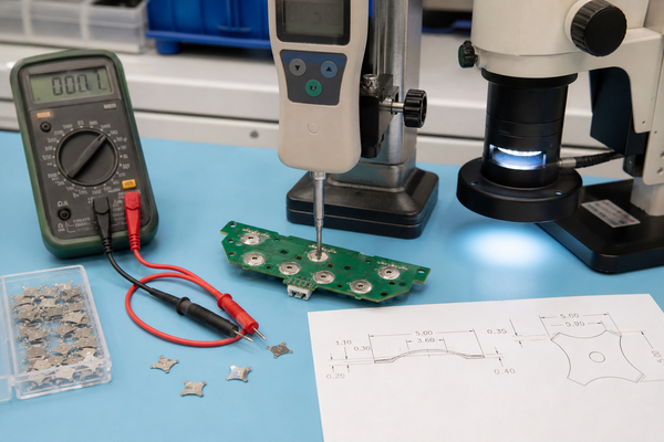
Test the sample in the intended PCB or FPC and actuator stack whenever possible. A bare-dome click test cannot confirm the effect of overlay stiffness, plunger geometry, board support or cavity venting. Record approved samples and force curves against the drawing revision so later production changes remain traceable.
Do not close open requirements silently. If the production package changes after sampling, identify whether the change affects fit, force, tooling, testing, price or lead time and issue a revised approval record.
FAQ About Metal Dome RFQ Checklist
Can a Hand Sketch Be Used for an Initial Quote?
Yes. A hand sketch can support an early engineering review or budgetary quote when it includes dimensions, dome positions, target force, quantity and the intended product form. Controlled CAD or drawing data is still needed before production tooling and release.
What If the Metal Dome Part Number Is Unknown?
Provide the available diameter or outline, target trip force, free height or travel, pad drawing, actuator geometry and an approved tactile sample if available. The manufacturer can compare standard series first and identify which requirements would force a custom part.
Should Force Be Specified in gf or N?
Either unit is acceptable when used consistently. State the nominal value, tolerance, test point and whether the measurement applies to the bare dome, dome array or complete keypad. Avoid mixing converted and measured values without identifying the source.
Is Annual Quantity Required for a Prototype RFQ?
It should be estimated even when uncertain. Prototype quantity determines the first build, while annual usage helps evaluate tooling, carrier processing, inspection and packaging methods. Mark the forecast as preliminary rather than omitting it.
When Should a Dome Array Be Quoted Instead of Loose Domes?
Quote a dome array when several domes need registered placement, when assembly errors must be reduced, or when the carrier must include adhesive, spacer, vents, cutouts or other functional layers. Loose domes remain practical when an existing structure retains them and the placement process is controlled.
Conclusion
A complete metal dome RFQ checklist connects the drawing, tactile target, contact design, array stack, environment, validation plan, quantities and packaging to one revision. This makes quotation assumptions visible and gives prototypes measurable acceptance criteria before production tooling or supply terms are fixed.
Send your drawing, dome or array requirements, target force, contact layout, quantities and test conditions through the Metal-Domes contact page or email sales@metal-domes.com. EBest Circuit(Best Technology) can review standard metal domes, custom dome arrays, SMD dome switches and the files needed for prototype or production quotation.