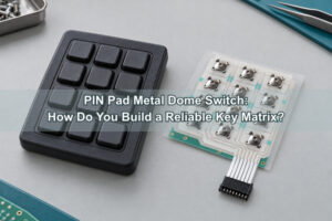

A membrane switch connector must match the tail's conductor pitch, contact count, exposed contact side, finished thickness, and termination material. Matching only the pin count is not enough: a tail can enter the housing yet make unreliable contact, reverse the circuit mapping, or damage the latch. Start with the exact mating connector drawing, then design the tail and PCB interface as a pair.
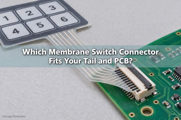
What Does a Membrane Switch Connector Connect?
The connector links the switch circuit to the controller PCB or wiring harness. It is separate from the metal dome or printed contact that closes when a key is pressed. The membrane switch tail carries those signals out of the keypad; its exposed end, attached terminals, or bonded joint forms the electrical interface.

A printed polyester (PET) tail may use silver traces with carbon-protected contact areas. A copper flex circuit uses a different conductor and laminate construction. Neither should be treated as interchangeable with a standard flat flexible cable simply because its outline looks similar. Confirm which termination materials the chosen connector accepts.
Membrane Switch Connector Types
Membrane switch connectors should be selected around the tail material, assembly access, and whether the keypad must be disconnected during service.
| Connection | How it connects | Main selection boundary |
|---|---|---|
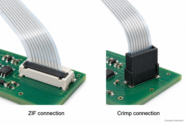
| ZIF socket | An open actuator allows tail insertion; closing it establishes contact and retention | Exact tail geometry, contact side, thickness, and actuator access must match |
| Non-ZIF insertion socket | Spring contacts engage as the tail is inserted | Insertion force and tail reinforcement must suit the approved construction |
| Crimp terminals in a housing | Dedicated terminals are mechanically attached to the flexible circuit | Terminal design, conductor material, tooling, and mating housing must be qualified together |
| Soldered copper flex or wired PCB termination | Copper pads connect to a board or wire assembly through a controlled soldering process | Requires solderable construction and a validated thermal process; not a default option for printed PET |
| Heat-seal or conductive adhesive bond | Heat and pressure form a bonded electrical interface | A process-specific joint, generally not a routinely detachable service connector |
An FFC/FPC socket's catalog label does not establish compatibility with every printed membrane circuit. The membrane switch connector specification should identify the exact part number and approved tail construction, not just a family name.
ZIF vs Crimp Connections
ZIF is useful when a compact tail can reach a PCB socket and the actuator remains accessible. Crimp connections suit designs that need a separate mating housing, but they add terminal attachment and housing-selection requirements.
| Decision | ZIF connection | Crimp connection |
|---|---|---|
| Assembly operation | Insert the tail as specified, then operate the actuator | Qualify terminal attachment, housing loading, and final mating |
| Space to reserve | Socket footprint, insertion path, and latch travel | Housing envelope, mating direction, and bend clearance |
| Retention | Connector locking mechanism plus external tail support | Housing retention or latching plus strain relief |
| Service life | Check the connector's mating-cycle rating | Check both terminal and housing mating-cycle specifications |
| Main prototype risk | Wrong contact face, thickness, or incomplete insertion | Poor crimp engagement, wrong terminal, or inadequate pull strength |
A switch's rated key-press life does not establish how often its connector can be unplugged. Specify these as separate requirements when the panel will be removed for cleaning, maintenance, or replacement.
How Do You Match Connector Pitch and Pin Count?
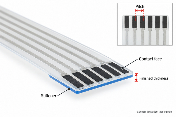
Pitch is the center-to-center distance between adjacent contacts, not the overall tail width. For a uniformly spaced row, estimate it by measuring from the center of the first conductor to the center of the last and dividing by one less than the number of conductors:
Pitch = first-to-last contact center span / (contact count – 1).
For example, eight contacts spanning 7 mm center to center have a 1 mm pitch. This is a geometry example, not a recommended membrane-switch specification. Check the production drawing for allowable pitch, conductor width, side margins, exposed length, and tail-edge tolerances.
Count electrical positions separately from visible keys. A passive 4 x 4 matrix can use four row lines and four column lines, while LEDs, shielding, or a different circuit arrangement can require additional positions. An eight-position housing therefore does not prove that two keypads have the same wiring.
Which Contact Side Must Face the Connector?
The exposed conductive face must meet the socket contacts. Top-contact, bottom-contact, and dual-contact designs are not automatically interchangeable, even when pitch and position count match. Check the connector's contact-location drawing against the installed PCB orientation.
Show the tail's conductive face and stiffener face on the assembly drawing. Identify the viewing direction used for pin 1, such as looking at the exposed contacts with the tail tip pointing upward. Then cross-check that view against the connector footprint. Flipping the drawing or folding the tail can reverse the apparent left-to-right order.
Do not infer the contact side from the latch color or housing appearance. During prototype assembly, verify orientation with the drawing and a continuity fixture before applying power.
Why Does Tail Thickness Matter?
The membrane switch tail connector is designed for a specified finished mating thickness. This includes the relevant film, conductor, coating, adhesive, and stiffener layers within the insertion area. Ordering a film of the correct nominal thickness does not establish that the finished tail meets the connector specification.
An undersized tail may have insufficient contact pressure or retention. An oversized tail may not seat fully and can overstress the actuator. Measure the finished insertion zone at defined locations, including its thickness tolerance; do not measure only the unsupported tail farther from the contacts.
A stiffener helps control thickness and handling, but its material, length, location, and adhesive must be included in the drawing. Check whether its transition falls outside the mating zone and whether the resulting step conflicts with the socket entrance. There is no universal stiffener thickness that fits all ZIF connectors.
How Do You Define the Membrane Switch Pinout?
Issue a pinout table that maps every connector position to a named net: row, column, LED anode or cathode, ground, shield, or intentionally unused position. Include the drawing view, pin-1 mark, revision, and mating part number. A connector with the correct mechanical fit can still produce wrong key codes if these assignments differ.
For a matrix keypad, test every key against its intended row-column pair. For illuminated keys, document LED polarity and the controller-side current-limiting arrangement. The connector's current rating does not establish the current capacity of a printed silver trace; qualify the complete conductor path and its operating conditions.
If the assembly includes an EMI dome array, define how its shielding reaches the designated ground or chassis connection. That path may use a specified connector position or a separate grounding feature. Do not silently join a shield to a scanning signal or assume the connector alone provides EMI protection.
How Should the Membrane Switch Tail Be Routed?
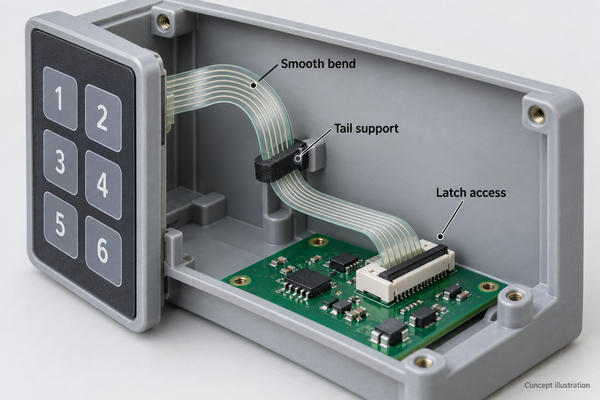
Route the membrane switch cable so enclosure movement cannot pull directly on the mating contacts. Reserve a smooth bend, support the tail before the connector, and keep the assembly path clear of screw bosses and sharp enclosure edges. Use the tail supplier's bend requirements for the actual laminate; do not apply one generic bend radius to every PET and copper-flex construction.
Leave room to open the actuator and insert or remove the tail according to the connector instructions. Some sockets have a specific insertion angle or locking sequence. A socket that fits the PCB layout may still be impossible to assemble after the board is installed.
Keep tail clamps, adhesive, and enclosure ribs away from active dome areas and required air paths. With a double-layer dome array, the carrier and spacer layout must be reviewed alongside the tail exit so support features do not obstruct dome movement or venting. This mechanical review does not replace electrical connector matching.
Can You Solder a Membrane Switch Tail?
Do not apply ordinary soldering-iron heat to a printed PET tail unless the complete construction has been explicitly designed and qualified for that process. The substrate, printed conductor, and termination may be damaged even if solder appears to attach briefly.
Copper flex tails and rigid PCB-based switch assemblies can use solderable pads when the surface finish, pad geometry, heat exposure, and mechanical support are specified. A copper-flex hot-bar joint is a controlled assembly process, not evidence that any membrane tail can be hand-soldered.
Heat-seal connections, including qualified anisotropic conductive film (ACF) joints, use their own material, pressure, temperature, and alignment requirements. Treat them as bonded interfaces with a defined rework procedure. If field replacement is required, compare that restriction with a detachable socket before releasing the design.
How Do You Test the Connector Before Production?
Use production-intent tail materials, stiffeners, and mating parts. A hand-cut sample with a different coating or thickness cannot validate the final interface.
- Check mechanical fit. Measure the mating zone, verify full seating and lock operation, and inspect for damaged edges or distorted contacts.
- Verify the complete pinout. Check open circuits, adjacent-net shorts, every key position, and LED polarity where applicable.
- Measure the right resistance. Separate connector contact resistance from the total resistance of printed traces, dome contacts, and the mating board. Define measurement points and acceptance limits before testing.
- Exercise the installed assembly. Monitor continuity while applying the specified handling, tail movement, or retention loads with the intended enclosure support in place.
- Repeat after relevant conditioning. Select temperature, humidity, vibration, and mating-cycle tests from the product environment and component ratings; record before-and-after results.
Approve the tail drawing and connector part number together. An alternate socket, new stiffener adhesive, or changed contact coating should trigger compatibility review rather than being accepted as a cosmetic substitution.
Why Does a Membrane Keypad Lose Contact?
Use the failure pattern to distinguish a connector problem from a key-contact or controller problem. Disconnect power before reseating, inspecting, or making resistance measurements.
| Observed problem | First checks |
|---|---|
| An entire row or column stops responding | Shared net continuity, tail seating, damaged contact finger, and corresponding PCB joint |
| Only one key fails | Local dome or printed contact, spacer alignment, and that key's trace path; do not assume the connector is responsible |
| Key codes are consistently wrong | Pin-1 reference, reversed contact view, row-column mapping, and controller configuration |
| Operation changes when the tail moves | Strain relief, incomplete locking, finished thickness, worn contacts, and cracks near the tail transition |
| Intermittent operation follows servicing | Mating-cycle history, latch damage, contamination, and tail insertion depth |
Inspect contact contamination using the approved cleaning procedure for the ink, plating, and plastics. Abrasive scraping or an unverified solvent can damage the contact surface. Replace a damaged latch or worn tail through the approved repair process instead of adding tape to force contact pressure.
What Should a Membrane Switch Connector RFQ Include?
For a custom dome-array integration review, send us the mating-interface details along with your keypad drawings. These inputs let us check the array layout against the proposed tail exit and confirm what is included in our quotation:
- Mating interface: connector manufacturer and full part number, drawing revision, pitch, positions, contact side, insertion direction, and required mating cycles.
- Tail drawing: material stack, finished mating thickness and tolerance, stiffener details, contact dimensions, coating, outline, length, and bend or support locations.
- Electrical definition: pinout with viewing direction, key matrix, LED and shield assignments, continuity requirements, and resistance measurement points.
- Assembly conditions: PCB and enclosure drawings, latch-access space, environmental requirements, prototype quantity, production quantity, and approved alternatives.
At EBest Circuit(Best Technology), we support custom dome arrays for customer-defined layouts and PCB or FPC integration. Send the dome locations, carrier outline, tail-exit clearance, and mating-interface details so we can review the array integration and confirm the supply scope. A connector-only replacement request also needs its exact mating specification; visual similarity is not a reliable substitute.
The right membrane switch connector matches both the finished tail and the controller interface, with routing and testing defined before production. Send your drawings, mating part number, and quantities to sales@metal-domes.com for a scoped engineering review and quotation.