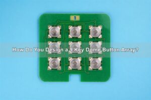
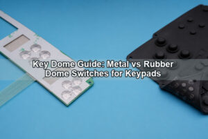
A PIN pad metal dome switch is the snap-action contact beneath one key in a PIN-entry keypad. It provides tactile confirmation and closes a PCB, FPC or membrane-circuit contact, but it does not encrypt a PIN or provide tamper security by itself. A reliable design must connect every key position to the correct electrical code while preventing neighboring keys, overlays and sealing parts from changing the intended tactile response.
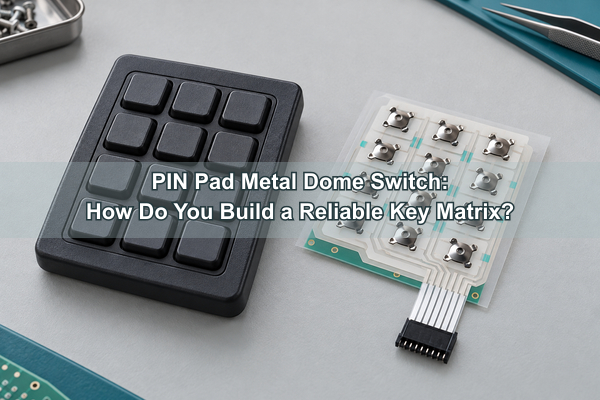
EBest Circuit(Best Technology) manufactures metal domes and custom dome arrays for payment terminals, access controls, safes, alarm panels and other PIN-entry interfaces. We evaluate dome geometry, carrier registration, contact layout and assembly method as one switching layer so the finished keypad can be verified key by key.
What Is a PIN Pad Metal Dome Switch?
The switching element is a formed stainless-steel dome that rests on an outer contact and snaps onto a center contact when pressed. The collapse creates a physical click and a momentary electrical connection. When pressure is released, the dome returns to its original shape and opens the circuit.
A PIN pad switch normally combines many of these contacts in a numeric layout. The dome controls tactile force, return and the physical contact event. The controller assigns each contact to a digit or function, applies debounce logic and passes the entry to the device’s secure electronics. Keeping these responsibilities separate prevents a tactile component from being mistaken for a complete secure PIN pad.
Search and purchasing teams may use PIN keypad or metal dome keypad for the complete user interface, while dome switch button may describe one tactile key position. The metal dome switch is the formed contact beneath that position; the keycap, circuit, controller and security functions remain separate parts of the finished device.
Where Are Metal Dome PIN Pads Used?
Metal dome PIN pads are used wherever a user enters a numeric code and needs clear physical confirmation. The switching requirements change with the enclosure, key style, expected duty and security architecture.
| PIN-pad application | Switching-layer priority | System responsibility outside the dome |
|---|---|---|
| Payment terminal | Consistent key confirmation, compact stack and repeatable key mapping | Encryption, tamper response, certification and transaction processing |
| Door access control | Outdoor sealing, glove operation and long-term key feel | Credential logic, relay control, enclosure rating and access records |
| Electronic safe | Low standby profile, positive actuation and reliable function keys | Lock control, audit logic, power management and tamper detection |
| Alarm or security panel | Distinct numeric and command-key zones | Alarm processing, communication and system supervision |
| Industrial PIN keypad | Cleaning resistance, mechanical guidance and serviceability | Machine authorization, safety logic and environmental enclosure |
The application name does not determine the dome specification. A countertop terminal and an outdoor gate keypad can use the same numeric arrangement while requiring different adhesives, key forces, sealing methods and validation conditions.
What Must Be Defined Before Selecting the Dome?
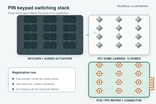
Start with the complete key map and physical stack, not a force value alone. The design input should include key pitch, keycap or overlay construction, actuator diameter, available height, target travel, PCB or FPC contact pattern, backing rigidity, sealing layers and the expected operating environment.
The key map should identify every digit plus Enter, Cancel, Clear and any application-specific command key. If different zones need different feedback, record separate tactile targets instead of relying on assembly variation. The drawing should also define mechanical datums that relate the carrier, circuit and enclosure to the same coordinate system.
How Does the Dome Layer Connect to a PIN Key Matrix?
Each dome bridges one normally open contact location. The circuit routes those locations into individual inputs or a row-column matrix. When a key is pressed, the controller detects one row-column intersection and maps it to the intended digit or function. The metal dome does not decide the code; it must create a stable contact at the correct coordinate.
A manufacturing drawing therefore needs both the mechanical position and the electrical key designation. Numbering domes only from left to right is insufficient when the circuit connector, keypad orientation or software key map uses a different reference. A controlled key-map table prevents a correctly assembled array from being connected to the wrong digit sequence.
| Drawing field | Example definition | Verification purpose |
|---|---|---|
| Mechanical key ID | K01 to K12 from one stated datum | Confirms physical position and inspection sequence |
| Displayed function | 0-9, Enter, Cancel | Links the user interface to the drawing |
| Electrical address | Row R1-R4 and column C1-C3 | Confirms circuit mapping without assuming software order |
| Dome specification | Approved part number and force zone | Prevents mixed-force placement errors |
| Test response | Expected continuity or scanner code | Supports fixture and final keypad verification |
How Can You Prevent Adjacent-Key or Double-Key Activation?
Adjacent-key activation begins when one press transfers force beyond the intended key center or flexes the shared circuit support. Risk increases when key pitch is tight, actuator guidance is loose, the backing plate is flexible or the top overlay bridges neighboring keys.
Control the force path with guided key stems or well-defined actuator areas, adequate separation between active zones, rigid support beneath the contact plane and a dome carrier that cannot shift. The center of the actuator should stay within the approved dome-loading region throughout normal off-axis presses. Neighboring domes should remain unloaded when one key is held at its practical edge.
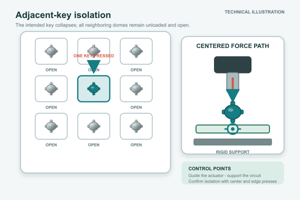
For a keycap that needs a controlled transfer point, our plunger dome array can combine registered domes with actuator features. The plunger dimensions still need to match the customer’s key travel, key guide and available stack height.
How Should High-Use Digits and Function Keys Be Balanced?
Key usage is rarely uniform. Enter, Cancel and Clear may use larger keycaps or different actuators, and some installations may subject particular positions to more frequent service use. The design should not infer or store real customer PIN patterns; it should validate every key position and define any intentionally different function-key zone.
Compare peak force, return force, travel and electrical response after assembly rather than accepting the loose-dome value as the finished-key value. If a larger Enter key uses the same dome as a numeric key, verify that leverage and guide friction do not produce a weaker or delayed feel. If a different force is intentional, the BOM and carrier artwork must make the distinction unambiguous.
When Is a Dome Array Better Than Loose Domes?
A registered array is usually preferable when the PIN layout has multiple closely spaced keys, mixed force zones or a low tolerance for placement mistakes. One carrier can hold the complete pattern, preserve orientation and reduce individual placement steps. It can also carry vent routes, adhesive keepouts and tooling features.
Our custom metal dome array can combine different dome sizes, shapes and forces on one PET carrier using customer CAD, PDF, Gerber, PCB or CAM data. Loose domes remain practical when the assembler has validated placement equipment, the quantities justify that process or service requires individual replacement. For prototypes or separated keys, a single-key dome array can reduce handling while keeping each unit independent.
How Do Metal Domes and Rubber Domes Differ in PIN Pads?
A metal dome provides a defined snap event in a very thin switching layer. A rubber dome keyboard or silicone keypad creates force and return through molded elastomer geometry, which can also provide sealing and key travel. Neither technology is automatically better for every PIN pad.
| Decision factor | Metal dome approach | Rubber dome approach |
|---|---|---|
| Tactile event | Sharp snap from the formed metal spring | Controlled by silicone geometry and material |
| Profile | Suitable for a thin tactile dome switch layer | Often uses more molded travel |
| Key guidance | Provided by overlay, plunger or enclosure structure | Can be integrated into the molded keypad |
| Assembly format | Loose dome, single-key unit or registered array | Molded keypad plus circuit interface |
| Selection question | Is a crisp, low-profile snap required? | Are molded travel, sealing and soft key geometry more important? |
A hybrid design can use silicone keys to transfer force onto metal domes. In that case, evaluate the molded actuator tip, silicone compression and dome position together instead of treating the metal and rubber parts as separate choices.
What PCB or FPC Contact Details Affect Key Registration?
The contact pattern must match the dome footprint, support the dome feet and provide a clean center contact. Surface finish, pad flatness, solder-mask clearance, contamination and board flex can change electrical response even when the tactile click feels normal. The circuit should be supported so one key press does not bend adjacent contact areas.
A four-leg metal dome can suit PCB, FPC and membrane constructions when the four feet and center snap area are correctly supported. Select the shape from the actual pad geometry and load path. Do not treat a generic metal dome PCB footprint as universal across dome series.
How Do Sealing, Venting and a PIN Pad Shield Affect Key Feel?
The exposed interface may include an overlay, silicone keypad, privacy hood or PIN pad shield. These parts can improve user privacy or ingress control, but they can also add pre-load, friction or uneven compression if they contact the moving keys. Privacy hardware should remain mechanically independent from the key travel unless that interaction is intentionally designed.
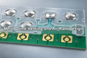
The sealed outer interface and the dome cavity have different jobs. The enclosure keeps liquid and debris away from the switching layer; the dome carrier still needs a controlled air path so each dome can collapse and return. Vent paths should remain inside the protected region, and final enclosure compression should not block them or squeeze adhesive into a key cavity.
What Production Inspection Catches Key-Matrix Errors?
Visual inspection alone cannot confirm that every displayed digit produces the correct electrical address. Production inspection should compare the physical key ID, expected row-column pair, actual fixture response and installed dome specification. This catches rotated arrays, connector reversals, mixed-force positions and circuit-map errors.
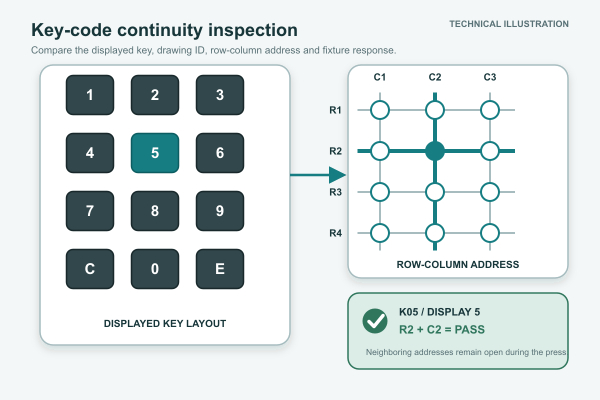
EBest Circuit(Best Technology) provides trip-force, rebound-force, lifecycle, electrical-performance and dimensional checks for the supplied dome or array. The customer’s keypad fixture should then verify the complete key map, connector orientation and controller response in the assembled product.
What Should a PIN Pad Prototype Test?
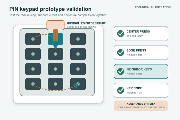
A useful prototype test reproduces the real keycap or overlay, circuit support, enclosure compression and electronic interface. Test every key at the center and practical off-axis locations, then confirm that adjacent keys stay open. Repeat representative digit sequences and command-key transitions without using or recording real user PIN data.
The plan should include key-code mapping, tactile spread, return behavior, contact bounce, held-key response, rapid sequential entry, cleaning exposure, temperature conditions relevant to the product and post-assembly dimensional checks. Acceptance criteria must come from the keypad specification and controller limits rather than a generic dome value.
What Should Be Included in a PIN Pad RFQ?
For our engineering review and quotation, send the information that defines the actual switch layer and its interface with the keypad:
- key layout, displayed functions and mechanical datum scheme;
- row-column matrix or individual-input map with connector orientation;
- PCB, FPC or membrane contact artwork and surface-finish requirement;
- keycap, overlay, silicone actuator or plunger drawings;
- target trip force, return force, click ratio, travel and separate force zones;
- carrier outline, registration holes, adhesive keepouts and vent routes;
- sealing, privacy hardware, cleaning agents and operating environment;
- prototype quantity, production volume, assembly method and validation requirements.
We can review whether loose domes, a registered array, plunger construction or single-key units provide the most controllable assembly. Send drawings and requirements to sales@metal-domes.com. The final PIN pad metal dome switch specification should connect every physical key to the intended electrical code and a measurable acceptance test.