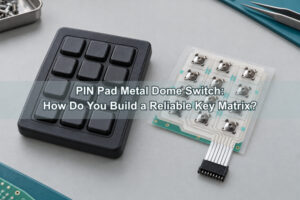
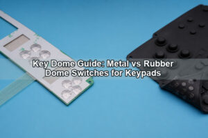
An ATM metal dome switch is the tactile spring contact beneath an ATM keypad key. It can provide a crisp actuation point and close a PCB or FPC contact, but it is not the complete encrypting PIN pad and it does not create payment security by itself. Reliable ATM input depends on the complete load path: keycap, plunger, travel stop, sealing layers, dome carrier, circuit contacts, enclosure and electronic scanning.
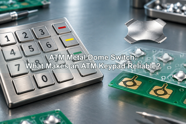
EBest Circuit(Best Technology) manufactures metal domes and dome arrays for ATM, POS and payment-device interfaces. For an ATM project, we review the dome as part of the keypad stack so that tactile force, alignment, overtravel, sealing and contact geometry can be validated together.
What Is an ATM Metal Dome Switch?
The switching element is a formed stainless-steel dome positioned over a normally open contact pattern. When the keycap or plunger applies force near the dome center, the crown snaps downward and bridges the circuit. On release, the dome recovers and opens the contact.
That simple movement has three jobs inside an ATM keypad: create a defined tactile event, provide a moving electrical contact and return the key after release. It should not be asked to absorb impact from kicking, striking or excessive key travel. Those loads belong to the keypad structure and its mechanical stops.
Where Does the Dome Sit Inside an ATM Keypad?
A typical load path begins at a stainless-steel or polymer keycap. A guided plunger or key stem transfers the press through a sealed interface to the dome. The dome sits on a registered carrier above PCB or FPC contacts. A rigid backing plate supports the circuit and keeps the contact plane stable.
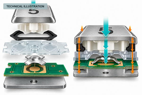
The layer order alone is not enough. The drawing must also define the plunger diameter, center offset, free gap, total key travel, stop position, dome height, carrier thickness and board support. A small tolerance change at each interface can become a large difference in force or pre-load at the dome.
What Does the Dome Layer Control, and What Belongs to the Secure Keypad?
ATM keypads are often part of an encrypting PIN pad or another secure terminal assembly. The dome supplier and keypad manufacturer must keep their responsibilities clear. A metal dome can support reliable tactile input, but encryption, tamper response and device certification belong to the complete secure assembly.
| Requirement | Dome or dome-array contribution | Complete keypad or EPP responsibility |
|---|---|---|
| Tactile confirmation | Trip force, return force, click ratio and travel | Keycap geometry, guidance, pre-load and user interface |
| Electrical input | Momentary bridge across the designed contacts | Matrix scanning, debounce, diagnostics and controller logic |
| Ingress control | Carrier, adhesive and dome-cavity air path | Fascia seals, drainage, enclosure joints and environmental rating |
| Mechanical abuse | Normal actuation within the approved travel window | Hard stops, backing structure and impact-load path |
| PIN security | No independent encryption or tamper-security claim | Cryptographic boundary, tamper protection and applicable device approval |
This separation prevents an important specification error: selecting a dome from tactile data alone and assuming the finished keypad will automatically meet security, sealing or abuse requirements.
How Should a Hard Stop Protect the Dome from Abuse?
A normal key press should collapse the dome and then reach a structural stop before excessive overtravel loads the dome beyond its approved deflection. In an ATM, the stop should be carried by the key guide, fascia, frame or backing structure rather than by the center of the dome.
When no positive stop is present, repeated heavy presses can flatten the crown, reduce return force, shift the tactile point or damage the PCB contact area. A stop that engages too early causes a different problem: the dome may not complete a stable electrical contact. Prototype testing therefore needs both nominal finger force and controlled overload conditions.
How Can the Keypad Maintain Consistent Feel Across Unequal Keys?
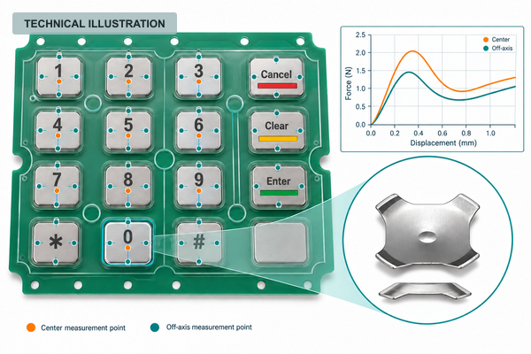
Numeric keys, Enter, Cancel and Clear may have different keycap areas, colors or shapes. Equal domes do not guarantee equal perceived feel because a longer keycap, off-center plunger or different guide friction changes the force reaching the dome.
Create a key-position force map rather than checking only one representative key. Record peak force, snap point, return force and total key travel at the center and at practical off-axis press locations. If function keys intentionally use a different tactile target, define them as separate zones instead of accepting uncontrolled variation.
For keys that require a guided load transfer, our plunger dome array options can combine registered domes with actuator features. The suitability of a plunger design still depends on key travel, available stack height and the customer’s enclosure tolerances.
How Should the Dome Array Register to the ATM Key Layout?
The array should use mechanical datums that relate directly to the PCB contact pattern and the keypad frame. Artwork edges alone are weak assembly references because die-cut, print and lamination tolerances can accumulate. Use registration holes, tooling features or defined carrier edges that the assembly fixture can locate repeatedly.
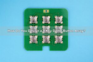
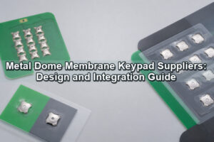
A custom metal dome array can hold multiple domes on one PET carrier at the required key coordinates. The array drawing should identify dome center positions, datum scheme, carrier outline, adhesive keepouts, vent routes and orientation features. Asymmetric tooling or a clear pin-one-style orientation mark helps prevent a 180-degree installation error.
What Contact Behavior Matters for PIN Entry?
The dome closes a physical contact, while the ATM controller decides how that event is interpreted. Contact resistance, bounce duration and release behavior must stay within the limits of the keypad electronics. A dome that feels normal can still produce an intermittent signal if the contact is contaminated, the board flexes or the center pad is not reached consistently.
Contact-pad finish, cleanliness, flatness and conductor geometry should be controlled with the dome footprint. A four-leg metal dome can suit PCB, FPC and membrane-switch constructions where its feet and central snap area are properly supported. Shape and force should be chosen from the actual contact pattern and load path, not from the ATM application name alone.
How Should Outdoor Sealing and Dome Venting Work Together?
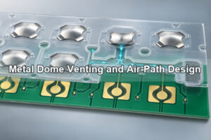
Outdoor or public-access ATMs may face rain, dust, spilled liquid and repeated cleaning. The enclosure seal should keep contaminants away from the switching layer, while the dome cavity still needs a controlled air path for press and release. These are different functions and should not be solved by opening an uncontrolled path through the keypad seal.
A suitable design can route air within the protected carrier or spacer region and terminate it in a dry internal volume. Adhesive squeeze-out, blocked channels and pre-load from the seal must be checked after final lamination and enclosure compression. Cleaning-fluid compatibility should be evaluated for the exposed key interface, seal and adhesive system; the metal dome alone cannot establish chemical resistance for the finished keypad.
Which Keypad Symptoms Can Be Mistaken for a Bad Dome?
Replacing the dome without identifying the system cause can allow the failure to return. The following diagnostic table separates likely switching-layer issues from surrounding keypad faults.
| Observed symptom | Possible dome-layer cause | Other causes to check |
|---|---|---|
| One key feels weak but still registers | Reduced return force, pre-load or off-center actuation | Key-guide friction, uneven stop height or warped support |
| One key clicks but does not register reliably | Contamination, carrier shift or unstable dome-to-pad contact | Trace, connector, scanner or debounce fault |
| Several keys in one row fail | Array or circuit alignment may affect a shared region | Matrix row, connector or controller fault |
| Key repeats without a second press | Contact bounce or slow dome release | Firmware timing, stuck keycap or guide friction |
| Key becomes intermittent after cleaning | Fluid reached the contact cavity or affected the adhesive | Damaged fascia seal, drainage or enclosure joint |
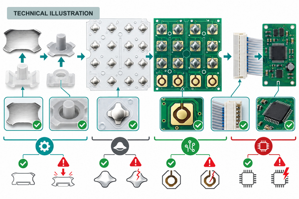
What Must ATM Keypad Prototype Testing Reproduce?
A bench press at the dome center is useful for component comparison, but it is not enough for an ATM keypad. Testing should reproduce the assembled keycap, guides, seal compression, PCB support and controller input conditions.
| Prototype test | What it reveals | Pass criteria source |
|---|---|---|
| Center and off-axis force map for every key zone | Guide friction, leverage, pre-load and tactile spread | Approved keypad tactile specification |
| Overtravel and controlled overload | Whether the hard stop protects the dome and PCB | Mechanical drawing and abuse-load requirement |
| High-use key cycling | Force drift, return behavior and contact stability | Product life target and defined test setup |
| Cleaning and ingress exposure | Seal leakage, adhesive response and contact contamination | Finished-keypad environmental specification |
| Electrical bounce and matrix scan check | Short contacts, repeats, missed entries and release timing | Controller and keypad electrical limits |
| Post-assembly force and resistance sampling | Variation introduced by lamination and housing compression | Production control plan |

EBest Circuit(Best Technology) can test trip force, rebound force, lifecycle behavior, electrical performance and dimensional accuracy for the supplied dome or array. Finished ATM keypad validation remains a joint task because enclosure, keycap, PCB and controller behavior are outside the dome alone.
Which Supply Format Fits ATM Assembly and Service?
Loose domes require the assembler to control every pick, orientation and position. A single-key dome array can suit widely separated keys or serviceable subassemblies, while a full custom array reduces individual placement steps and keeps the complete numeric layout registered on one carrier.
The selection should follow assembly volume, field-replacement strategy, tooling, circuit format and allowable handling risk. A complete array is not automatically better if the keypad must be serviced as separate modules; loose domes are not automatically cheaper if inspection and placement losses dominate the assembly cost.
What Should Be Included in an ATM Keypad RFQ?
For our engineering review and quotation, send us the information that defines the actual switching layer rather than only the phrase “ATM keypad.” Useful inputs include:
- PCB or FPC contact artwork, key coordinates and mechanical datums;
- keycap and plunger drawings, including diameter, stroke and off-axis conditions;
- target trip force, return force, click ratio, travel and any separate function-key zones;
- available stack height, free gap, pre-load and hard-stop location;
- carrier outline, adhesive keepouts, venting concept and seal-compression condition;
- operating environment, cleaning agents and required lifecycle or electrical tests;
- prototype and production quantities, assembly method and service strategy.
We can review whether a loose dome, single-key unit, plunger construction or custom array provides the most controllable solution. Send the drawings and requirements to sales@metal-domes.com. The final ATM metal dome switch specification should connect tactile data to the actual keypad load path, circuit and verification plan.