Metal dome membrane keypad suppliers integrate tactile metal domes with carrier films, printed circuits, graphic overlays, connector tails and optional lighting or shielding layers. The important distinction is supply scope: some sources provide only loose domes, while others build a registered dome array or a complete keypad subassembly. A reliable design must coordinate dome geometry, key pitch, contact pads, venting, actuator alignment, adhesive, sealing and enclosure support as one system.
What Is a Metal Dome Membrane Keypad?
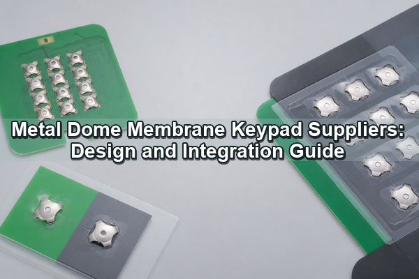
A metal dome membrane keypad is a low-profile user interface in which a formed stainless-steel dome supplies both tactile snap and momentary electrical contact. The dome sits over a printed silver circuit, copper flex circuit or PCB contact pattern. Pressing the key collapses the dome and bridges the center and outer contacts; releasing it lets the dome recover and reopen the circuit.
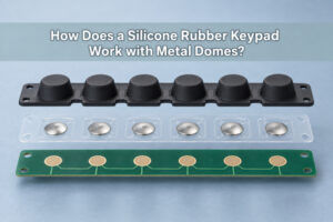
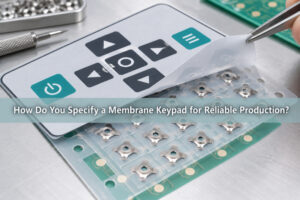
The keypad is more than the dome. A typical stack also contains a printed polyester or polycarbonate overlay, a spacer or dome-retainer layer, pressure-sensitive adhesive, a circuit tail and connector, and a rigid support surface. Optional layers can add backlighting, EMI/ESD control, environmental sealing or a plunger that concentrates load on the dome crown.
This architecture suits equipment that needs a thin interface, an audible or tactile click, sealed graphics and a custom key layout. It differs from a molded rubber keypad because the metal dome supplies the snap action, and it differs from a mechanical tact switch because the circuit, labels and multiple keys can be integrated into a laminated panel.
What Can Metal Dome Membrane Keypad Suppliers Deliver?
Supply scope can stop at the tactile component or extend to a completed keypad layer. The correct boundary should match the party that controls circuit artwork, overlay graphics, final lamination and enclosure integration.
| Supply level | Included elements | Control that remains outside the part |
|---|---|---|
| Loose metal domes | Dome shape, size, plating and force characteristics | Placement, retention, pad design, venting and overlay |
| Dome array | Pre-positioned domes, carrier, adhesive and die-cut outline | Circuit, graphic overlay and final keypad lamination |
| Functional tactile layer | Array plus spacer, venting, actuator, shielding or lighting layer | Final graphics, connector or enclosure depending on scope |
| Complete keypad subassembly | Overlay, tactile layer, circuit, tail and selected backer | Host electronics and enclosure mounting |
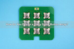
A custom metal dome array is useful when several keys must maintain fixed X-Y coordinates and orientation during installation. The drawing should still state which layers are included, because the term “membrane keypad” does not define the circuit type, connector, backer, backlighting or environmental seal by itself.
How Does a Metal Dome Membrane Keypad Stack-Up Work?
Each layer performs a different mechanical, electrical or environmental function. The overlay carries legends and provides the touch surface. A top adhesive bonds it to the spacer or tactile layer. The spacer creates enough cavity height for dome travel and can form vent channels. The dome array positions the metal contacts. The circuit supplies the contact pads and signal traces, while the rear adhesive or backer fixes the assembly to its support.
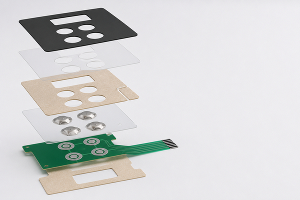
Total thickness is not the only stack-up variable. The dome cavity must allow free collapse and return without preload. Adhesive cutouts must not intrude under the dome feet. The circuit and backer must remain sufficiently flat, and the overlay must transfer load near the center of each dome. Small errors across several layers can shift the force curve even when every individual part is within tolerance.
Use one coordinate system for overlay keys, embossing, dome centers, contact pads, circuit tail and mounting features. Tooling holes or enclosure datums should be carried through every released artwork file so that registration can be inspected before final lamination.
Which Dome Geometry and Force Range Fit the Keypad?
Dome geometry must fit the available key area and contact pattern. Circle domes are compact and symmetric. Four-leg domes provide defined support points and open sectors that can assist vent routing. Triangle domes fit three-point layouts, while oblong domes suit elongated keys or narrow control panels. The matching contact-pad layout must be developed for the selected dome series rather than copied from a generic drawing.
Trip force alone does not define the finished feel. Travel, rebound force, click ratio, dome diameter, actuator diameter, overlay stiffness, backer rigidity and keycap leverage all contribute. Record the loose-dome force curve and the assembled-key force curve separately. The comparison shows whether variation comes from the formed dome or from the surrounding keypad stack.
- Choose dome outline and diameter from the available pad area, key pitch and enclosure clearance.
- Set force and travel from the intended finger input and false-activation risk.
- Define the actuator contact face so load remains near the dome center.
- Use the enclosure or an equivalent rigid fixture when approving finished tactile response.
How Should the Graphic Overlay and Embossing Align with the Dome?
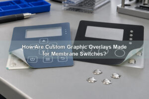
The printed key legend, embossed area and dome center should share the same datum. Pillow embossing creates a raised key area, while perimeter embossing defines the boundary with less central film deformation. Either method must leave enough flat material for adhesive bonding and must not push the dome into a preloaded state when the keypad is at rest.
Key pitch must accommodate the dome footprint, spacer wall, vent channel, adhesive land and overlay graphics. Crowding adjacent cavities can weaken the spacer or connect vents unintentionally. A wide key needs an actuator or internal geometry that directs off-center finger load toward the dome crown; otherwise the key may feel different depending on where it is pressed.
Overlay material and thickness affect stiffness, chemical resistance, print durability and light transmission. These properties should be evaluated together with emboss height and dome force. A stiffer overlay can increase apparent actuation force or reduce tactile ratio even when the dome itself is unchanged.
How Should PCB or FPC Contacts, Venting and Tails Be Designed?
The circuit contact pattern normally separates a center contact from an outer contact region. The dome rests on the outer area and bridges to the center when collapsed. Uneven plating, solder-mask steps, exposed vias, contamination or circuit flex can prevent stable seating and create intermittent contact. Pad center, dome center and allowed registration error should be dimensioned on the same drawing.
Venting lets air leave the key cavity during actuation and return during release. Channels can route through the spacer or between the legs of a compatible dome. They must not terminate in a sealed pocket, cross an adhesive dam without control or create an unintended path for liquid. Multi-key keypads also need a deliberate decision on whether cavities share a vent network or remain isolated.
For an FPC or printed-silver tail, define tail exit direction, conductor pitch, stiffener length, bend zone and connector orientation. Keep the first bend outside the stiffener and away from the keypad bond line. If the tail exits through a housing slot, include enough strain relief so enclosure assembly does not peel the laminated keypad.
When Should a Single-Layer, Double-Layer or Plunger Array Be Used?
The array format should add only the functions that the keypad actually requires. A single-layer dome array minimizes thickness and part count when the carrier can retain the domes directly and the substrate already controls clearance and venting. A double-layer dome array adds a spacer around the domes, creating defined cavities and more controllable air paths.
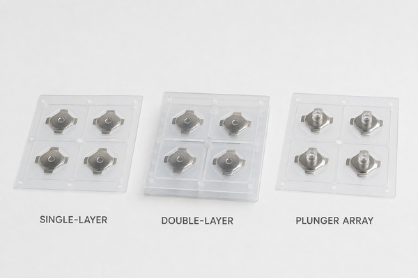
| Array option | Function | Critical design check |
|---|---|---|
| Single-layer | Basic dome retention and registration | Adhesion, cavity clearance and external vent path |
| Double-layer | Spacer-defined cavity and vent routing | Total thickness, cutout alignment and adhesive lands |
| Plunger array | Concentrated load transfer and added height | Plunger diameter, height, concentricity and overtravel |
| Rubber-glue array | Bond interface for rubber key or selected substrates | Material compatibility and environmental aging |
A plunger dome array is appropriate when a flat overlay, molded key or enclosure feature does not load the dome predictably. For rubber-key integration, a rubber-glue dome array can provide a compatible bond interface. Both options alter the mechanical stack and must be validated in the final keypad support structure.
How Can Backlighting, EMI Control and Environmental Sealing Be Added?
Backlighting can use discrete LEDs, a light guide film or another optical layer. An LGF metal dome array distributes light across a thin keypad region, but the optical pattern must match LED position, graphic windows, key spacing and local stack height. EBest Circuit(Best Technology) publishes LGF thickness of approximately 0.125 mm for suitable designs, subject to optical and mechanical qualification.
An EMI-printed dome array adds a conductive silver or silver-carbon layer to a single- or double-layer construction. That layer only contributes to shielding or ESD control when its grounding path, resistance and contact location are defined. A conductive print with no controlled connection to chassis or circuit ground is not a complete protection strategy.
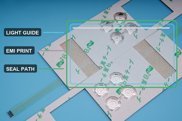
Environmental sealing depends on the complete perimeter, tail exit, windows, vents and enclosure interface. A sealed front overlay does not prevent moisture entry through a poorly designed tail slot or shared vent. Define the exposure type, cleaning chemicals and temperature range, then validate adhesive, films, conductive inks and printed graphics after conditioning.
Which Manufacturing Files Control a Custom Membrane Keypad?
A controlled release package should keep the mechanical layout, circuit artwork, graphic artwork and layer stack synchronized. EBest Circuit(Best Technology) can evaluate custom dome-array data supplied as AutoCAD, PDF, Gerber, PCB/CAM files or customer drawings. Dimensions and revisions still need to be explicit; a screen image is not a substitute for controlled coordinates.
- Mechanical drawing: overall outline, key centers, tooling features, cutouts, datums and tolerances.
- Layer stack: film, adhesive, spacer, circuit, backer and nominal total thickness.
- Dome definition: series, shape, size, force, travel, orientation and mixed-force position map.
- Circuit data: contact pads, traces, tail, stiffener, connector and electrical matrix.
- Graphic data: legends, colors, windows, embossing and print-side identification.
- Functional options: vent routes, LGF pattern, LED positions, shielding print and ground connection.
All files should carry matching revision identifiers. A change to the overlay key center can invalidate the dome position; a new connector can move the tail stiffener; a different adhesive can change total thickness and bond behavior. Revision control should extend to tooling, inspection data and approved samples.
Which Tests Verify Tactile and Electrical Consistency?
Inspection begins with layer dimensions, key coordinates, dome orientation, circuit alignment, tail geometry and die-cut quality. Visual inspection should also detect contamination, carrier creases, adhesive intrusion, blocked vents and damaged release liners. Electrical continuity confirms contact closure and isolation, but it cannot show whether the key has the correct tactile response.
Force testing needs a defined probe diameter, support fixture, speed and travel limit. Measure trip force and rebound force under the same method, and compare the loose dome with the completed keypad. Life-cycle testing should use the intended load point and stroke. EBest Circuit(Best Technology) publishes trip-force measurement, rebound-force measurement and dome life-testing capability for its metal dome and dome array products.
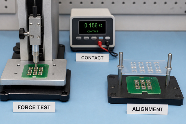
Environmental qualification should check the functions that can drift after heat, humidity, UV exposure or cleaning: bond strength, graphic appearance, contact resistance, key force and return behavior. The related metal dome quality and testing controls provide context for component validation, while the finished keypad must also be tested in its intended enclosure.
How Should a Membrane Keypad Be Installed in the Enclosure?
The mounting surface must be clean, flat and rigid enough to support every dome. Registration pins, a fixture or camera targets should reference the same datums used in the released drawing. Remove the release liner without stretching the keypad, align the part before the adhesive contacts the surface, then apply uniform pressure from one side to avoid trapped air.
Do not use the dome as an enclosure travel stop. A hard key or plunger needs guidance and a controlled end stop so excessive force is carried by the housing. The circuit tail should enter its connector without sharp bending, torsion or peel load at the keypad edge. After installation, check perimeter bond, tail strain relief, key return, contact closure and force consistency before the enclosure is sealed.
The earlier membrane keypad design guide provides additional layer and layout context. Installation approval should use the production enclosure or a fixture with equivalent flatness, support and actuator geometry.
How Should Supplier Scope Be Compared Without Creating Gaps?
Compare scope by assigning ownership for every interface. If one source supplies the overlay and another supplies the dome array, the released package must identify who controls their alignment. If the circuit comes from a third source, its pad finish, dimensional tolerance and tail connector must be verified against the tactile layer. A sample can feel acceptable even when these responsibilities remain undefined, so approval criteria must be measurable.
Useful scope boundaries include dome forming and plating, array lamination, circuit printing or etching, graphic printing, backlighting, connector termination, final lamination, electrical test and tactile test. Ask for evidence only for the functions included in the supplied part. For example, an array supplier can verify dome position and force, but cannot guarantee enclosure sealing unless the enclosure and final assembly are within the agreed scope.
Metal dome membrane keypad suppliers are easiest to compare when the same drawing, stack-up, test method and acceptance limits are used across samples. This keeps design responsibility visible and prevents a change in one layer from being mistaken for a dome-quality issue.
FAQ About Metal Dome Membrane Keypad Suppliers
Can a metal dome membrane keypad use a PCB or an FPC?
Yes. Metal domes can close contacts on a rigid PCB, copper flex circuit or printed membrane circuit. The pad geometry, surface flatness, support rigidity, tail design and installation method must match the selected circuit.
What is the difference between a dome array and a complete membrane keypad?
A dome array positions metal domes on a carrier film. A complete membrane keypad normally adds the graphic overlay, spacer, circuit, adhesive layers, connector tail and any required backer, lighting or shielding.
Can one keypad use different dome forces?
Yes. A custom array can combine different dome sizes, shapes or forces when each position is identified in the drawing and the carrier provides enough room for retention, venting and die cutting.
Does a higher trip force always create a stronger click?
No. Perceived click also depends on rebound force, click ratio, travel, actuator geometry, overlay stiffness and support rigidity. The completed keypad should be measured in its intended stack.
Can a metal dome membrane keypad be backlit and sealed?
Yes, but both functions require system design. Backlighting needs coordinated LEDs, optical films and graphic windows. Sealing requires a controlled perimeter, tail exit, vent strategy, adhesives and enclosure interface.
Conclusion
A dependable metal dome membrane keypad requires more than choosing a dome force. The overlay, embossing, spacer, array, contact pads, vent paths, circuit tail, lighting, shielding and enclosure support must remain aligned through production and installation. EBest Circuit(Best Technology) has manufactured metal domes and metal dome arrays since 2006 and supports single-layer, double-layer, EMI-printed, rubber-glue, LGF, plunger and custom array constructions. For a technical review of a keypad application, use the Metal Dome and Dome Array contact page.