
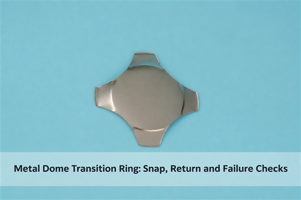
The metal dome transition ring is the formed boundary where a snap dome’s raised crown changes into its supporting edge or legs. It is part of the same stamped metal sheet, not an added ring. This region bends as the dome snaps and helps the spring recover when the load is removed. A dome that clicks weakly, returns slowly or stays down may have damage at this boundary, but the actuator, support and PCB clearance must also be checked before blaming the dome.
What Is the Transition Ring on a Metal Dome?
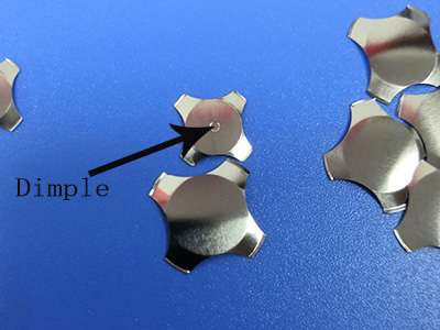
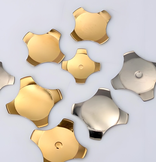
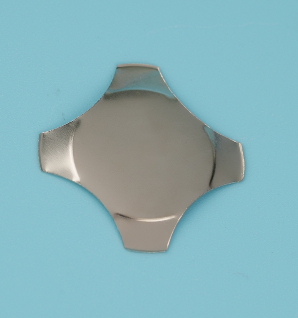
The transition ring is the curved zone around the crown where its radius meets the supporting perimeter. On a four-leg dome, that perimeter continues into four feet; on a round dome, it continues into the rim. It may appear as a narrow circular line under suitable lighting, although the exact visibility and contour depend on the stamping and finish.
Do not confuse it with a center dimple, the PCB’s outer contact ring or an adhesive retaining layer. The dimple is near the crown center when a design includes one; the transition region sits nearer the support. When inspecting a part, first identify the crown, then follow the curvature outward to the change in slope. Look for local kinks, dents or asymmetry there rather than treating every reflection line as a defect.
How Does the Ring Shape Snap Action?
The transition region flexes as a centered load drives the crown toward the contact pad. The dome initially resists the load; after the trip point, its geometry changes rapidly and the force drops. That change in force is the mechanical source of the familiar click. The transition region works with the whole formed crown and the support boundary, so its outline alone cannot specify a trip force.
Compare parts with a force-displacement trace taken on the same fixture, actuator and support geometry. Mark the trip force, displacement at snap and force drop. If two samples look similar from above but their traces differ, check material, thickness, crown height, forming condition and how their feet or rim are supported. A photograph cannot replace the trace.
Read the trace in the same direction as the press. A peak followed by a drop identifies the snap event; an unusually small drop can explain a weak tactile response even when the electrical contact closes. Keep the electrical make point on the same displacement axis so a design review can see whether the switch closes before, during or after the tactile event.
What Makes a Metal Dome Spring Back?
After a normal press, stored elastic energy in the formed metal returns a momentary dome toward its initial shape. The transition region is a critical flexing zone in that return path. Release force is not the same measurement as trip force: it is observed on the unloading portion of the force-displacement curve, under a defined fixture and speed.
A useful return check is mechanical and electrical. Release the actuator fully, observe whether the crown recovers, and confirm that the PCB contact opens within the specified response. A dome can appear to recover yet remain electrically closed because of pad contamination, an adhesive constraint or a depressed actuator. Conversely, an open circuit alone does not prove healthy spring return if the support or alignment has changed.
Transition Ring vs Center Dimple and Support Legs
These features do different jobs. A center dimple, if present, changes the local contact or actuation geometry. Legs or a continuous rim provide the boundary against the PCB. The transition ring connects the crown to that boundary and sees repeated flexure during snap and recovery.
The distinction matters during failure analysis: a worn center contact can cause intermittent conduction while the spring still returns; a bent foot can tilt an otherwise undamaged crown; a dent near the transition can change the snap or return behavior. Record the damaged location before selecting a corrective action, because replacing the dome will not cure an uneven PCB seat or an actuator that strikes its edge.
| Observed location | Possible effect | First check |
|---|---|---|
| Center/dimple | Contact or local actuator response changes | Center pad condition and strike point |
| Transition region | Trip or return curve shifts | Dent, crease and force-displacement trace |
| Foot/rim | Support becomes uneven | Coplanarity, PCB seat and adhesive clearance |
How Much Travel Is Too Much?
Too much travel is any movement beyond the specific dome and assembly’s approved stroke; there is no safe universal number. For many conventional domes, forcing the crown below the plane of its supporting feet risks permanent deformation near the transition region. That warning is not a blanket rule for every series: some round-dome designs are specified for overtravel applications, so the actual part drawing and test method control.
Measure the entire stack: actuator free height, cover compression, adhesive or spacer thickness, dome height and PCB pad height. Then compare the worst-case actuator stop with the dome supplier’s permitted travel for that part. A hard stop outside the dome load path can keep an enthusiastic user press from turning the dome into the mechanical stop. Verify the assembled stack at tolerance limits, not just nominal dimensions.
If the drawing does not state an allowable stroke, do not assign one from a different dome style. Request the part-specific force-displacement data and stop position, then trial the actual keypad at maximum cover compression. After the trial, remeasure release force and resting height; electrical continuity alone would miss a spring that is already losing its return margin.
Why Do Off-Center Loads Damage Return?
An off-center or sharp actuator makes the dome bend asymmetrically instead of loading its crown as intended. One portion of the transition region may see greater strain while the opposite support remains less engaged. A fingernail or pointed tool can also leave a local dent. The resulting click and recovery may vary with the user’s press position.
For a repeatable check, press with the specified actuator at the intended location, then repeat at realistic edge positions allowed by the keypad. Compare force-displacement curves and electrical make/break behavior. If edge presses fail while centered presses pass, inspect alignment, actuator face shape and support stability before changing the dome force grade.
How Do PCB Support and Adhesive Affect the Ring?
A flat, correctly located support lets the formed dome flex and recover as designed. Debris under a foot, a raised trace, excess adhesive or an uneven retaining film can preload one side and alter the effective boundary. The transition region then works under a different constraint from the one used to characterize the loose part.
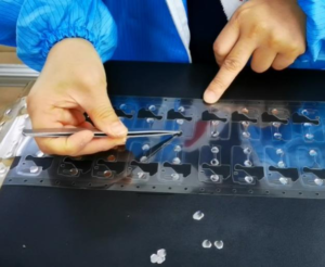
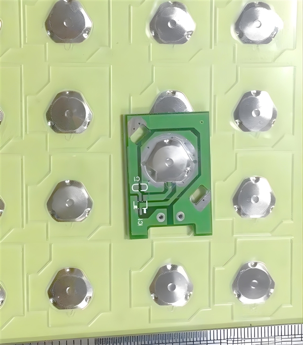
Test both the loose dome and the assembled switch. A loose part that passes but an assembled key that sticks points toward stack geometry, placement or contamination. In an array, check whether the carrier film holds the dome centered without pressing on the active flexing zone. Our metal dome array page shows the carrier-and-PCB arrangement; the required clearance must still be set for the chosen dome and drawing.
For a row of keys that behaves inconsistently, map each failed location to its pad and film position. A pattern near one edge suggests placement or support variation; random failures that move with loose parts suggest part variation. This map gives a stronger corrective-action lead than increasing the specified force across the whole keypad.
What Does a Damaged Transition Ring Look Like?
Look for a localized crease, flattened arc, dent or uneven curvature at the crown-to-support boundary. Also compare the dome’s resting height and symmetry against an unused part from the same specification. Surface reflections can mislead, so rotate the sample under consistent lighting and inspect both sides if the part can be handled without further damage.
Do not declare failure from appearance alone. Measure trip force, return force, travel and contact opening on the same fixture before and after cycling or suspected damage. If the dome remains down after release, separate intentional bistability from a failed momentary dome by checking the approved part specification; the appearance of two positions is not enough to establish a designed bistable function.
How Should Snap and Reset Be Tested?
Use a fixture that reproduces the part’s intended support and a centered actuator with a documented tip shape. Record loading and unloading force versus displacement, then repeat after a defined number of cycles. The result should include the trip point, release behavior, any residual set and whether the PCB circuit makes and breaks at the required points. Test speed, temperature and dwell time belong in the record because changing them can change the curve.
For an assembly problem, use a three-way comparison: unused loose dome, suspect loose dome, and suspect dome installed in the stack. A shift already present in the loose suspect part supports a dome-level issue; a shift only after installation points toward support, adhesive or actuator conditions. This is a diagnostic method, not a universal pass/fail limit. Acceptance values must come from the approved drawing or validated design specification.
Keep the same fixture and test sequence for all three conditions. Record the part identifier, pad drawing revision, actuator geometry and measurement settings with each trace. If the traces cannot be compared on a common basis, an apparent force change may come from the test setup rather than the transition region.
| Symptom | Compare | Likely next action |
|---|---|---|
| Weak click, normal return | Trip force and force drop against approved sample | Check dome forming and actuator alignment |
| Slow or absent return | Release curve, resting height and electrical opening | Inspect transition area and overtravel stop |
| Loose dome passes, assembly sticks | Loose and installed curves | Check pad flatness, film and adhesive clearance |
| Only edge presses fail | Center and permitted edge strikes | Check actuator face and position tolerance |
Which Dome Style Fits the Support Geometry?
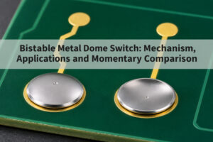
Choose the dome style from the switch stack, not from the visibility of its transition ring. A four-leg metal dome has distinct support feet and may suit PCB layouts that need contact traces beneath the dome. A round metal dome uses a continuous perimeter and can suit different space and support constraints. Their forming, permitted stroke and contact layouts are not interchangeable.
Provide the PCB pad drawing, overlay and actuator stack, target trip and release behavior, allowed travel, operating environment and required cycle test when comparing candidates. Ask for a force-displacement trace under the intended boundary conditions. A sample that feels right in the fingers may perform differently in the finished keypad, especially when the support and actuator change.
Metal Dome Transition Ring FAQs
Is the transition ring a separate component? No. It is a formed zone of the snap dome itself. A visible circular line marks a change in curvature, not an additional ring that must be assembled.
Can a damaged dome be pressed back into shape? Do not treat manual reshaping as a qualified repair. It can hide a changed force curve or create a new local bend. Replace the suspect part and correct the cause of excess travel or uneven loading, then retest the assembly.
Does every dome have the same reset force? No. Release force depends on the selected geometry, material and fixture. Compare samples against a part-specific, documented specification rather than a generic number.
For a switch that must click and reopen reliably, evaluate the transition region together with the full load path and PCB stack. At EBest Circuit(Best Technology), we can review the relevant dome or array options against your drawing and target force-displacement behavior. Contact us at sales@metal-domes.com with the part geometry and assembly details, and keep this metal dome transition ring guide as the inspection reference.