
Choosing among rubber keypad manufacturers requires more than comparing a molded sample and unit price. A capable supplier should confirm who owns the silicone molding, contact system, PCB or FPC interface, legends, coating, backlighting, assembly and final test. Before tooling begins, the drawing package must connect key geometry, tactile response, electrical closure, enclosure fit and environmental requirements to measurable acceptance criteria.
What Should Rubber Keypad Manufacturers Confirm Before Tooling?
The supplier should first confirm the product boundary. Some projects need only a molded silicone mat, while others require conductive pills, a printed or etched circuit, metal domes, a graphic overlay, backlighting, connector termination and final assembly. Cost and responsibility cannot be compared fairly until every supplier is evaluating the same deliverable.
We review the key layout, section drawing, circuit interface, enclosure support, operating environment, cosmetic standard, prototype quantity and expected production volume before recommending the contact construction. Missing dimensions or unclear responsibility should be resolved before a mold or assembly fixture is released.
Rubber Keypad Manufacturers vs Membrane Switch Suppliers
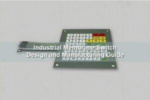
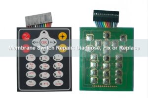
A rubber keypad manufacturer normally focuses on molded silicone geometry, color, legends, conductive contacts and surface treatment. A membrane switch supplier may control printed films, spacers, circuits, adhesives and tails. The right partner depends on whether the product is a standalone rubber mat or an integrated user-interface assembly.
| Supplier scope | Typical responsibility | Buyer must confirm |
|---|---|---|
| Molded rubber keypad | Silicone body, web geometry, color, legends and conductive pills | Who supplies and tests the mating PCB or FPC |
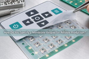
| Membrane switch assembly | Overlay, spacer, printed circuit, tail, adhesive and optional domes | Whether molded silicone parts are included or customer-supplied |
| Integrated keypad assembly | Rubber keypad, contact system, circuit, lighting and assembly validation | Which tests apply to parts and which apply to the installed product |
Through our related silicone rubber keypad and membrane-switch operation, we can coordinate molded keypad requirements with the metal dome, dome array, circuit and overlay interfaces instead of treating those parts as unrelated purchases.
Which Silicone Material and Hardness Requirements Matter?
Material selection starts with the operating temperature, cleaning chemicals, UV exposure, compression set, color and flame or regulatory requirements of the finished device. Shore A hardness is useful, but it does not define the key feel by itself. Web thickness, web angle, key travel, top geometry and preload can change the force curve even when the same silicone compound is used.
The released specification should identify the material family, hardness target and tolerance, color standard, surface finish and any required test method. If a special compliance grade is required, the exact compound and supporting declaration should be approved rather than inferred from a generic material description.
How Should Tooling, Key Geometry and Web Design Be Reviewed?
The mold drawing should show key centers, overall outline, key height, travel, web geometry, draft, radii, undercuts, venting, parting lines and critical cosmetic surfaces. The section through each key type is especially important because two keys with similar top views can produce different force and return behavior.
We also compare the molded part with the enclosure and circuit datums. A keypad can pass dimensional inspection as a free part yet bind after installation if the frame opening, compression stops, screw locations or support ribs load the silicone unevenly.
Which Contact System Should the Manufacturer Build Around?
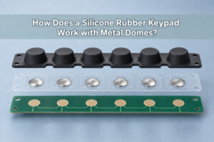
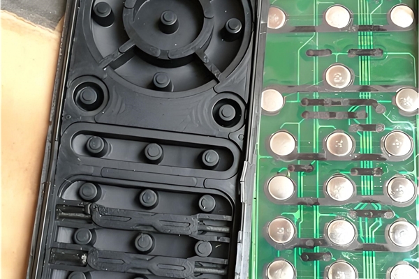
The contact system determines how the mechanical press becomes an electrical signal. Carbon pills and printed conductive coatings can bridge PCB contacts directly. Metal domes add a defined snap event and can be supplied as loose domes or a positioned array. The choice should be made from contact resistance, tactile response, available height, pad geometry, assembly method and life requirements.
| Contact option | Strong fit | Critical interface check |
|---|---|---|
| Carbon pill | Molded silicone key directly closes PCB contacts | Pill diameter, PCB pad pattern, resistance and contamination control |
| Conductive coating | Low-profile or geometry-specific conductive area | Coating adhesion, resistance uniformity and wear |
| Metal dome | Distinct snap feel and repeatable switching point | Dome diameter, force, travel, PCB pad and actuator alignment |
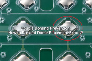
| Dome array | Multiple domes need controlled location and faster assembly | Carrier datum, adhesive keep-out, venting and circuit registration |
When Should a Rubber Keypad Use a Metal Dome Array?
A metal dome array is useful when the rubber key acts as an actuator but the required snap response comes from a dome below it. The keypad plunger must contact the intended dome area without excessive side load, and the circuit must support the dome perimeter and center contact correctly.
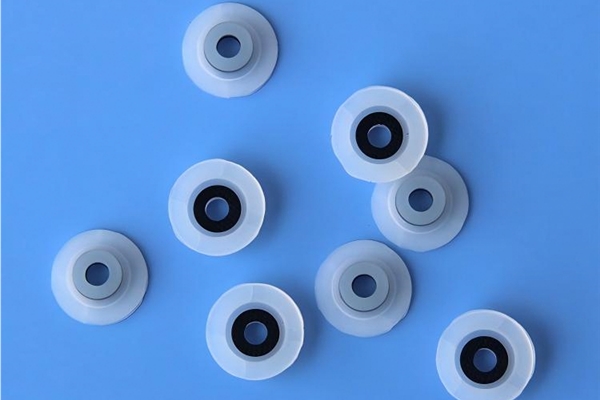
Our rubber-glue dome array is designed to bond to a keypad or PCB. Its published product range lists 0.28-0.45 mm total height, 0.13-0.30 mm travel and 100-400 gf force, with the final construction selected for the actual dome, carrier and adhesive stack. When a molded key cannot reach the dome reliably, a plunger dome array can provide a controlled load-transfer feature rather than relying on an improvised spacer.
How Are Legends, Colors and Protective Coatings Controlled?
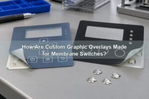
Legend durability depends on the marking process and the surface the operator touches. Options include pad printing, screen printing, laser etching and molded color features. A protective coating may improve abrasion or chemical resistance, but it must be qualified with the selected ink, silicone and cleaning method.
Release artwork should identify the color reference, font, line weight, legend position, acceptable registration and cosmetic inspection limit. A color chip or approved physical sample is more useful than relying only on how a color appears on a monitor.
What Backlighting Options Can a Manufacturer Support?
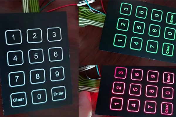
Backlighting can use direct LEDs, translucent silicone, laser-etched legends, light-guide film or combinations. The manufacturer should evaluate LED position, key-wall leakage, opaque masking, legend brightness, color consistency and the effect of the lighting stack on key travel.
For a thin illuminated tactile interface, our LGF dome array combines a light-guide film with the dome carrier. Lighting uniformity still needs a prototype using the actual LED locations, legend artwork, enclosure and viewing conditions.
How Should the Keypad Interface With PCB, FPC and the Enclosure?
The keypad, circuit and enclosure must share a functional datum system. Key centers, contact pads, windows, mounting holes, compression stops and tail exits should be dimensioned from the same references. The circuit should also define pad finish, trace routing near contacts, connector orientation and any keep-out needed for adhesive or mechanical support.
Enclosure compression must hold the keypad in place without preloading the keys. Local gaps can weaken sealing, while excessive compression can raise force, reduce travel or keep a dome partially loaded. Stack tolerance should therefore be checked at the worst-case high and low conditions.
Which Tolerances Must Be Defined on the Drawing?
Critical tolerances are those that affect fit, actuation, contact and appearance. They commonly include overall outline, key center position, key and web dimensions, height and travel, contact location, carbon-pill diameter, legend registration, tail location and hole position. Not every cosmetic dimension needs the same tolerance as the switching geometry.
The drawing should separate molded-part tolerances from assembled alignment tolerances. It should also identify the inspection state: free part, installed part or complete switch assembly. Without that distinction, suppliers and customers may measure a flexible component in different ways and obtain different results.
Which Prototype Tests Should Be Completed Before Tooling Approval?
Prototype approval should combine mechanical fit, tactile response, electrical closure and cosmetic review. A free keypad sample can confirm color and molding quality, but assembled testing is needed to evaluate force, travel, return, contact resistance, lighting and enclosure compression.
- Inspect the molded part, legends, color and critical dimensions against the released drawing.
- Measure assembled key force and travel at representative positions.
- Confirm electrical closure and resistance with the actual PCB or FPC contact pattern.
- Check for key interference, preload and uneven enclosure compression.
- Evaluate lighting uniformity and light leakage when backlighting is included.
- Run the required environmental and life tests with documented pass criteria.
How Do You Evaluate Quality Control and Production Consistency?
Production control should connect approved materials, tooling revision, artwork, process records and inspection results to the shipped lot. Buyers should ask which dimensions are measured, how tactile and electrical samples are selected, how cosmetic limits are applied and how changes to compounds, inks, coatings or sub-suppliers are controlled.
We prefer acceptance criteria that can be repeated: a drawing revision, defined test method, sampling plan and approved reference sample. Statements such as “good feel” or “close color” are not adequate when multiple lots or multiple key positions must remain consistent.
What Changes Cost, MOQ and Lead Time?
Tooling complexity, part size, number of colors, insert molding, carbon pills, laser etching, coatings, backlighting, circuit type, assembly content, inspection requirements and production volume all affect cost. A supplier quoting only the molded rubber part will naturally look different from one quoting a tested keypad-and-circuit assembly.
Lead time should be separated into design review, tooling, first-article samples, revision loops and production. If several variants share a common base, identify which features are common and which require separate tools or artwork so the commercial plan reflects the actual product family.
Rubber Keypad Manufacturers FAQs
What is the difference between a rubber keypad and a membrane switch?
A rubber keypad is a molded elastomer component with physical keys. A membrane switch is a layered switching assembly built from films, spacers and a circuit. They can be used separately or combined in one interface.
Can a silicone rubber keypad use metal domes?
Yes. The molded key can actuate a metal dome positioned on a PCB, FPC or dome-array carrier. Reliable operation requires matched key travel, actuator diameter, dome force, pad geometry and enclosure support.
Do rubber keypad manufacturers need the enclosure drawing?
The enclosure drawing is strongly recommended because bezel clearance, compression, support ribs and mounting features affect key travel, sealing and tactile response. A keypad cannot be fully validated from its standalone drawing alone.
When should carbon pills be replaced by a metal dome?
A metal dome is worth evaluating when the product needs a sharper snap, a defined switching event or a positioned array. Carbon pills remain practical when the molded rubber web and direct PCB contact already meet the feel, resistance, life and height requirements.
What Information Do We Need for a Rubber Keypad Project?
Send the 2D drawing and 3D model, key-section details, silicone and color requirements, legend artwork, contact choice, PCB or FPC files, enclosure drawing, force and travel targets, backlighting needs, environmental conditions, prototype quantity and expected production volume. Mark any item that is still open for engineering review.
When you compare rubber keypad manufacturers, ask each supplier to evaluate the same controlled package. At EBest Circuit(Best Technology), we can review the molded keypad interface together with metal domes, dome arrays, PCB or FPC contacts and optional light-guide features, then identify the prototype checks needed before production. Send the files to sales@metal-domes.com to request an engineering quotation.