The key difference in a momentary vs latching switch is what the contacts do after you release the actuator. A momentary switch returns to its normal contact state. A latching switch keeps the selected state until another deliberate action changes it. Neither the shape of the button nor an illuminated indicator reliably identifies the mechanism.
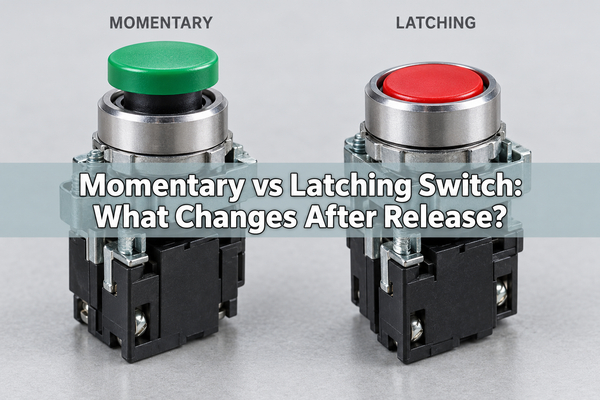
For a keypad or control panel, choose the contact action separately from the behavior of the equipment. A momentary button can command a controller to keep a light or motor running; the controller, not the button, retains that state.
What Is the Difference Between Momentary and Latching Switches?
Compare the released state, not just the pressed state. The examples below start with an open contact; normally closed and changeover versions also exist.
Check
Momentary switch
Latching switch
While operated
Changes contact state while the actuator is held
Changes the selected contact state
After release
Returns to its normal state
Retains the selected state
Next operation
Repeats the temporary action
Changes the state again, depending on the mechanism
Typical control task
Keypad entry, a reset command, or a hold-to-run input
A maintained mode selection or push-on/push-off control
Where state is retained
Not in the ordinary switch mechanism; downstream electronics may retain it
In the switch mechanism; downstream electronics may add further control
The important distinction is between a brief input and a maintained contact selection. A latching pushbutton may use alternate action, while a maintained toggle stays in its selected position. Check the actual operating sequence rather than assuming every latching device releases with a second press.
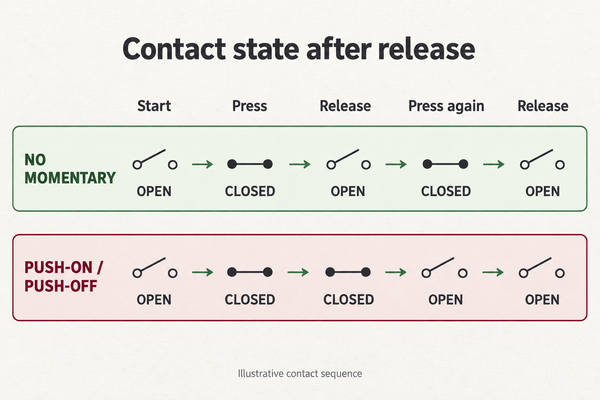
What Do NO, NC and (ON) Mean?
NO means normally open: the contact is open in the specified normal, unoperated condition. NC means normally closed. These describe contact states, not whether the switch is momentary or latching. A momentary switch can have NO contacts, NC contacts, or a changeover contact with both.
In many switch catalogs, parentheses identify a momentary position. An OFF-(ON) switch returns from ON when released; an ON-OFF-ON switch normally has three maintained positions. An (ON)-OFF-(ON) device has a maintained center position and two momentary end positions. Confirm the manufacturer's notation and contact diagram for the exact part number before ordering.
SPST and SPDT describe the number of poles and selectable contact paths. They do not establish whether the mechanism springs back. A purchase description such as "SPDT pushbutton" is incomplete without its contact action and terminal arrangement.
Are Push Buttons and Toggle Switches Always Latching?
No. Push button and toggle describe how the user operates the switch. Momentary and latching describe what happens to its contacts after operation. Both pushbuttons and toggles can be supplied with momentary or maintained action.
A momentary switch vs toggle switch comparison therefore mixes two different attributes. Specify both, such as "spring-return toggle, center OFF" or "momentary push button switch, normally open." For a momentary vs latching push button switch, compare the action code and contact sequence even when the housings look identical.
Actuator height is not conclusive either. Some alternate-action pushbuttons return to the same external height after each press while the contacts alternate internally. Use the datasheet or a continuity test, not a photograph, to identify their action.
Momentary vs Latching Switch Wiring
A momentary vs latching switch wiring diagram must match the terminal configuration, contact rating, and load circuit. Two-terminal switches can look interchangeable yet produce different behavior because one returns after release and the other stays selected. An illuminated switch may also have separate LED terminals that must not be mistaken for contact terminals.
For a low-voltage controller input, a common arrangement connects an NO contact between the input and ground, with a pull-up holding the input high when the contact is open. A momentary contact then produces a temporary low level; a maintained contact holds the low level until its position changes. Verify the controller voltage limits, pull-up requirements, and intended logic before using that arrangement.
A logic input is not a power output. If the switch commands a motor, solenoid, or other substantial load, the circuit may need a rated driver or relay and appropriate transient suppression. Select switching ratings for the actual AC or DC load, including inrush and inductive behavior. Do not use a contact rating from a different load category as an equivalent.
Use the terminal drawing for COM, NO, NC, and illumination connections. Terminal count alone does not reveal the pinout, and a generic diagram is not a substitute for the selected component's wiring instructions. Mains wiring requires an appropriately rated assembly and qualified installation.
Can a Momentary Switch Stay On?
The switch normally returns after release, but its controlled output can stay on. A debounced press can change a stored bit in a microcontroller or toggle logic circuit. A separate driver then operates the load. This is electronic latching, not a mechanically latching button.
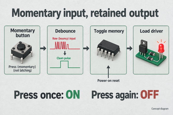
Mechanical contacts can bounce during one operation. Without suitable filtering, one press may be interpreted as several transitions. Define one valid press event, reject bounce, and prevent another toggle until the button has been released. Choose debounce timing from the component and assembled-product behavior rather than treating one delay as universal.
The control circuit must also have power when it needs to detect a press. If the button turns off the supply that powers its own sensing logic, a simple software toggle cannot wake the product by itself. That design needs an appropriate always-powered input or a dedicated power-control arrangement.
What Happens After a Power Failure?
A mechanically latching switch usually retains its selected position through a loss of power. When the supply returns, a connected load may therefore restart unless another control prevents it. The switch retains a contact selection, not electrical energy.
An electronically retained output may reset, restore a saved state, or remain undefined during startup unless the circuit and firmware establish its behavior. Specify the required startup state explicitly. "Remember the last state" and "always restart OFF" are different requirements and need different implementation and testing.
Test loss and restoration of power with the output both ON and OFF, including a button held during startup. Where an unexpected restart could cause harm, use the required safety architecture and rated devices. A generic momentary input, metal dome, or software toggle is not by itself an emergency-stop system.
Are Metal Dome Switches Momentary?
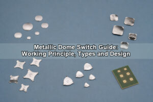
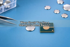
An ordinary metal dome is a momentary spring contact. Pressing it causes the formed metal to deflect and connect the intended contact areas; releasing it allows the dome to return. For example, a round metal dome can bridge an isolated center contact to the surrounding contact when pressed. The tactile snap does not create a retained ON state.
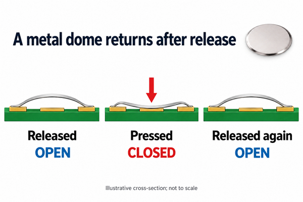
A dome-based ON/OFF key normally needs downstream state control if one press should turn the equipment on and the next should turn it off. For surface-mount integration, an SMD dome switch provides a different mounting format, not automatic latching behavior. Confirm the selected model's assembly process, contact rating, and operating force; do not assume a loose dome is suitable for solder reflow.
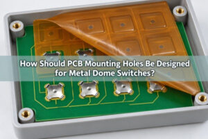
With custom dome arrays, we can review the carrier outline and dome positions against the PCB or FPC layout. The mechanical stack must allow each dome to release: actuator preload, excessive travel, misalignment, or restricted movement can prevent correct return. Check the installed overlay, actuator, support, and venting arrangement as a complete assembly. A dome that remains closed because it is trapped or damaged is a fault, not an acceptable latching mechanism.
How Do You Test the Switch Action?
Check an unpowered, isolated component with a continuity meter. Disconnect all supplies and make sure stored energy is discharged before resistance testing. If the switch remains connected to a circuit, parallel paths can produce misleading readings.
- Identify the contact terminals from the component drawing. Keep LED terminals separate.
- Measure the selected contact pair with the actuator released and record whether it is open or closed.
- Operate the switch, keep it held, and record the changed state.
- Release it completely. A return to the starting contact state indicates momentary action for that position; a retained state indicates maintained action.
- Operate it again or use its specified release mechanism. Check every position and pole, then repeat the sequence in the installed assembly.
A continuity beep can confirm basic action but cannot prove the absence of contact bounce, acceptable resistance under load, or rated switching life. Use appropriate electrical measurement and application testing for those requirements. If the bench switch releases correctly but the installed button does not, inspect mechanical preload and clearances before changing the electronics.
Which Switch Action Should You Choose?
Start with the required behavior after release and after a power interruption. Then select the actuator, contacts, mounting, and electrical ratings. Do not choose action merely because a button looks like a familiar power switch.
| Required behavior | Suitable starting point | What to verify |
|---|---|---|
| One command per keypress | Momentary input with event handling | Debounce, release detection, and any deliberate repeat function |
| Output active only while held | Momentary contact or monitored input | Release response and the application's safety requirements |
| A persistent physical mode selection | Maintained toggle, rocker, or latching selector | Contact state mapping and startup behavior |
| A thin keypad with push-on/push-off behavior | Momentary metal dome plus electronic state control | Reset policy, standby power, and user-visible state feedback |
| A control that must not restart unexpectedly | Defined reset or restart-inhibit architecture | Power-cycle testing and any required safety-rated design |
For a dome-based interface, send us the contact layout, actuator geometry, available travel, operating-force target, electrical sensing conditions, and expected life. Include the required press/release sequence and power-up behavior so the mechanical interface and controller specification do not contradict each other.
FAQ
Can You Convert a Latching Switch to Momentary?
Replace it with the correct momentary-action part when the same footprint or housing family offers one. Do not remove or defeat an internal latch unless the manufacturer explicitly supports that configuration; modification can invalidate mechanical behavior and ratings. Detecting an edge from a maintained switch in software also does not make the physical switch spring-return.
Does an Illuminated Button Show the Actual Output State?
Only if its indicator is driven to represent that state. An LED wired directly to the supply may remain lit while the controlled output is OFF. For an electronically latched function, define whether illumination indicates power available, a command received, or the actual load state.
Does a Momentary Switch Last Longer Than a Latching Switch?
There is no universal winner. Compare mechanical and electrical life for the specified load, operating conditions, and mechanism. A low-current keypad contact and a switch interrupting an inductive load cannot be compared using cycle count alone.
The practical momentary vs latching switch choice is whether the contacts must return or remain selected, and where any retained equipment state should reside. At EBest Circuit(Best Technology), we can review the metal dome or dome-array portion of your interface. Send the contact drawing and operating requirements to sales@metal-domes.com for a scoped design and quotation review.