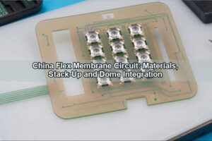
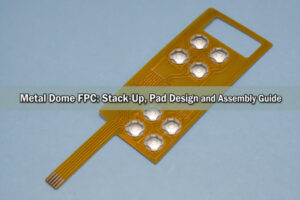
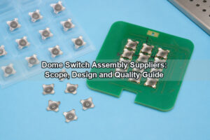
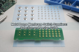
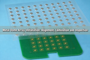
A metallic dome in this guide is a thin stamped stainless-steel tactile contact used in a keypad, membrane switch, PCB or FPC assembly. It is not an architectural dome. The part combines a spring element and a normally open electrical contact: pressing it through its snap point connects the center pad to the outer contact, while release restores the original shape and opens the circuit.
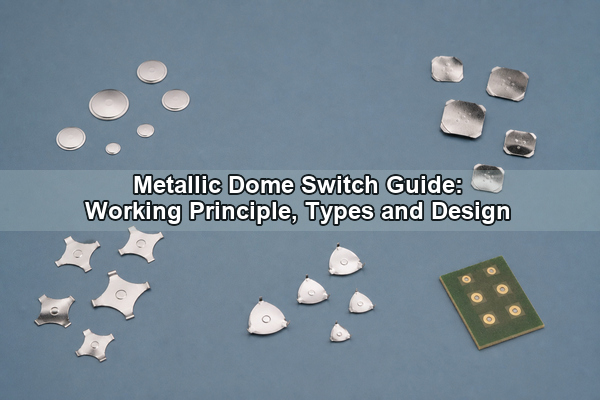
What Is a Metallic Dome?
A metallic dome is a preloaded spring contact formed from thin stainless steel. Its curved profile stores elastic energy. When an actuator applies sufficient force, the crown moves through an unstable point and snaps downward. This event produces the sharp force drop that a finger recognizes as tactile feedback.

The basic metal dome structure includes a crown, a perimeter or several support legs, a central contact area and optional features such as a center dimple, vent notch or positioning tabs. The PCB completes the switch: the outer pad supports and electrically connects the dome, while the center pad closes the circuit only after the crown collapses.
Because the dome is both spring and conductor, its geometry cannot be selected independently from the pad layout, actuator diameter, stack height or adhesive carrier. A shape that feels correct on a rigid test fixture may behave differently beneath a thick overlay or on a flexible circuit.
How Does a Metallic Dome Switch Work?
A metal dome switch begins in the open state. The perimeter touches the outer PCB electrode, but the crown remains above the center electrode. Applied force rises until it reaches trip force. The dome then snaps down, the center contact touches the PCB pad and resistance falls to the closed-circuit level. On release, the spring recovers and separates the contacts.
The useful force-displacement curve has four engineering points: initial preload, peak or trip force, post-snap force and return force. The difference between peak and post-snap force creates the tactile drop. If the actuator continues too far after contact, it can overstress the dome, wear the surface finish or transfer unnecessary load into the PCB.
Electrical closure is therefore only one requirement. A stable metal dome switch must also return consistently, avoid chatter at the trip point and preserve its force curve through the required cycle count and temperature range.
Which Metallic Dome Shapes Are Available?
Shape affects support, venting, available contact area and the direction in which the dome can be loaded. The PCB land pattern should be designed around the selected shape rather than copied from a different series.
| Shape | Useful characteristics | Design attention |
|---|---|---|
| Round metal dome | Compact, symmetric response and broad size availability | Needs a continuous, flat outer support ring and an unobstructed vent route |
| Four-leg metal dome | Defined support points, useful vent sectors and positive orientation | Each leg must land on the intended pad without adhesive beneath it |
| Triangle metal dome | Fits compact triangular or three-contact layouts | Actuator and pad must remain centered relative to all three supports |
| Oblong dome | Fits narrow interfaces and elongated key geometry | Off-axis loading is more critical along the long dimension |
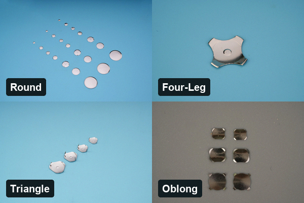
Dimensions and force ranges vary by series. A smaller footprint can reduce available travel and make alignment more sensitive, while a larger dome requires a wider support area and sufficient clearance from nearby traces, components and enclosure ribs.
How Do Trip Force, Travel and Click Ratio Interact?
Trip force is the maximum force reached immediately before snap-through. Travel is the actuator movement required to reach electrical contact. Click ratio expresses the force drop after the peak, commonly calculated as the difference between trip force and contact force divided by trip force. A higher ratio generally feels sharper, but it does not automatically mean better control.
A heavy key with short travel may feel abrupt, while a light key under a thick overlay can feel muted because part of the finger force is consumed by the overlay and adhesive stack. The design should therefore define force at the assembled interface, not only the free-dome value. Actuator stiffness, diameter, preload and overtravel all change the perceived response.
Force tolerance also matters across a multi-key panel. Mixing dome lots, allowing unequal support heights or varying the adhesive opening can produce keys that measure within individual part tolerances but feel inconsistent when compared side by side.
Which Stainless-Steel and Plating Options Matter?
Spring-grade stainless steel is used because it can sustain repeated elastic deformation while maintaining corrosion resistance and dimensional stability. Material thickness and heat treatment are tied to the formed geometry; substituting a nominally similar sheet without revalidating the force curve can shift trip force, travel and fatigue life.
Surface treatment is selected according to the electrical contact system and environment. Bare or passivated stainless steel can suit many low-current keypad applications. Nickel or gold contact finishes may be specified when contact resistance, oxidation exposure or low-level signals require tighter control. Plating must remain compatible with forming and must not crack or flake at the high-strain zones.
The mating PCB finish is part of the same contact pair. ENIG, hard gold or another qualified finish should be selected with the expected current, contamination risk, cleaning process and cycle requirement in mind. A metal tactile dome should never bridge residues, soldermask ridges or rough plating at its support points.
How Should PCB Contact Pads Be Designed?
The contact pattern needs a center electrode and an electrically separate outer electrode. For a round dome, the outer electrode normally forms a support ring. For a four-leg dome, separate support lands can correspond to the legs. The center pad should be large enough to tolerate placement error but small enough to preserve isolation before actuation.
Keep soldermask, silkscreen, vias and abrupt copper steps away from the bearing surface. A support height difference can tilt the dome and shift the force curve. A narrow vent path should let air move out from beneath the dome without allowing adhesive to creep into the contact area. Trace exits should not create a local ridge under a support point.
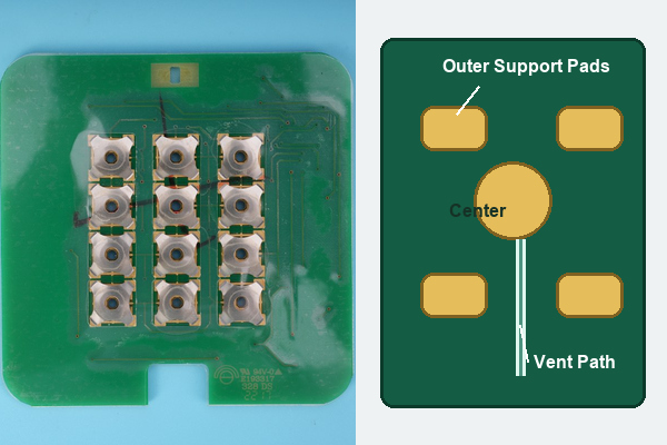
For low-level signals, contact resistance should be evaluated after the actual cleaning, lamination and environmental exposure processes. A visually clean pad can still carry ionic residue or adhesive contamination that destabilizes the closed resistance.
How Are Metallic Domes Mounted?
Loose domes can be placed directly on a PCB and retained by an overlay, spacer or housing feature. This approach is economical for simple layouts but requires controlled placement and retention. Peel-and-place sheets add handling efficiency for individual positions, while a registered array fixes multiple domes beneath a die-cut carrier.
A custom metal dome array aligns dome centers, adhesive openings, vent channels and assembly datums in one part. It is particularly useful when key pitch is tight or the circuit is flexible. SMD dome switches provide a package suitable for automated placement and reflow when the thermal profile, package construction and board design are qualified together.
Regardless of mounting route, the dome must sit flat, remain centered and have free space to move. Adhesive should retain the carrier around the dome rather than restrain the active crown or wick beneath a support edge.
Loose Metallic Dome vs Dome Array vs SMD Dome Switch?
| Format | Best fit | Main control points |
|---|---|---|
| Loose metallic dome | Simple products, repairable assemblies or low position counts | Placement, retention, orientation and contamination |
| Dome array | Multi-key membrane panels, FPC keypads and repeatable registration | Datum scheme, adhesive cutouts, venting and lamination tolerance |
| SMD dome switch | Automated PCB assembly and compact reflow-compatible designs | Land pattern, stencil, placement force, reflow profile and wash restrictions |
The correct format follows the assembly process. A loose dome is not automatically lower cost once manual placement and inspection are included. An array adds tooling and carrier material but can reduce alignment variation. An SMD package supports automation but introduces solder and reflow controls that do not apply to an adhesive array.
Which Actuator and Support Conditions Matter?
The actuator should contact the dome near its geometric center and present a smooth, controlled surface. A tip that is too small concentrates stress; a tip that is too wide can contact the fixed perimeter before the crown completes its motion. Side load causes asymmetric collapse and can permanently distort a leg or edge.
Stack-up calculations should include overlay thickness, spacer thickness, carrier thickness, PCB-to-housing tolerance and any actuator preload. A hard stop is useful when the enclosure could otherwise drive the dome far beyond its electrical contact point. The underlying PCB or FPC also needs uniform support, because local bending absorbs travel and changes the apparent force.
For tall interfaces, a separate plunger can transfer force from a keycap to the dome, but its guide clearance and tilt must be controlled. The contact surface should not scrape the crown during lateral key movement.
What Causes Metallic Dome Failure?
- Off-center loading: one leg or edge carries excessive strain, causing force drift or permanent deformation.
- Excessive overtravel: the crown is flattened beyond its intended elastic range and loses return force.
- Uneven pads: soldermask, copper steps or debris tilt the dome and produce intermittent contact.
- Blocked venting: trapped air slows actuation or changes the force curve, especially under a sealed overlay.
- Contact contamination: adhesive, ionic residue, dust or corrosion increases resistance and causes chatter.
- Incorrect actuator geometry: a sharp, oversized or misaligned plunger damages the active crown.
Failure analysis should preserve the entire stack. Examining only the removed dome can miss a pad-height error, enclosure rib, adhesive intrusion or unsupported flex area that created the damage.
How Are Metallic Domes Tested?
Dimensional inspection verifies diameter, height, leg position, flatness and orientation features. A force-displacement tester records trip force, contact force, return force and travel, while a synchronized electrical channel confirms the closure point and detects bounce. Contact resistance should be measured at the intended test current rather than inferred from continuity alone.
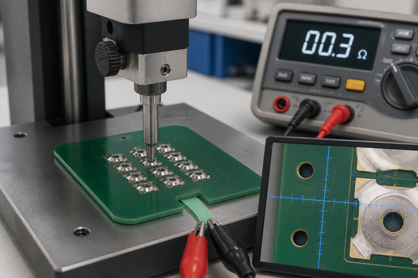
Life cycling should use the production actuator diameter, alignment, support and overtravel. Environmental verification can include temperature exposure, humidity, corrosion resistance and post-aging force/contact measurements. EBest Circuit(Best Technology) supports metal dome, dome array and integrated PCB/FPC configurations; the company profile documents product-dependent trip-force options across a broad 100–6000 gf portfolio and cycle targets that must be confirmed for the selected shape and stack.
Sampling should compare initial and post-test force curves, not only count electrical closures. A dome can still conduct while losing the tactile drop required by the interface.
FAQ About Metallic Domes?
Is a metallic dome conductive?
Yes. The stainless-steel dome forms a conductive bridge between the outer and center PCB electrodes when actuated. The allowable signal level depends on the contact system, finish and contamination control.
Is a metal dome the same as a rubber dome?
No. A metal dome is a spring contact that can provide both tactile response and electrical closure. A rubber dome supplies elastic return and normally presses a separate carbon pill or conductive contact.
Can a metallic dome be used on FPC?
Yes, provided the FPC has a stable backing at the key area, a compatible pad finish, controlled bend zones and a carrier or overlay that keeps the dome registered.
How long does a metallic dome last?
Life depends on shape, force, material, actuator alignment, overtravel and environment. The cycle requirement should be verified in the complete production stack rather than assigned from dome geometry alone.
Conclusion
A metallic dome performs reliably only when its spring geometry, force curve, PCB contact pattern, actuator and mounting method are designed as one system. Select the shape first, then validate pad support, venting, assembled travel and post-cycle electrical performance. For application-specific dome or array support, contact EBest Circuit(Best Technology) at sales@bestpcbs.com.