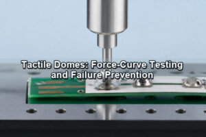
A key dome is the resilient element beneath a keycap, graphic overlay or keypad button that provides return force and tactile feedback. It may be a stamped stainless-steel metal dome, a molded rubber dome or a formed polymer dome. The material and geometry determine how the key feels, while the surrounding actuator, spacer, circuit contact and housing determine whether that feel remains consistent in the finished assembly.
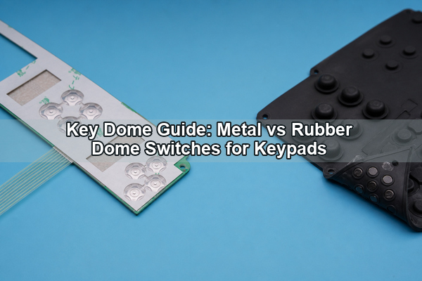
What Is a Key Dome?
A key dome converts vertical finger movement into a spring response. In a metal design, the stainless-steel dome can also bridge a center and outer PCB electrode to close the circuit. In a rubber design, the elastomer normally carries a carbon pill or pushes a separate conductive contact onto the circuit.
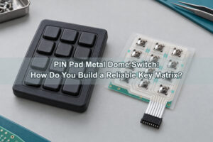
The term describes a component inside an interface, not the complete key. A finished dome switch button can include a molded keycap, guided plunger, graphic overlay, adhesive spacer, dome carrier, PCB or FPC, backplate and enclosure. Each layer changes preload, alignment, travel and acoustic response.
A keyboard dome switch may prioritize low cost and quiet travel, while an industrial keypad may require a sharper tactile event, a sealed overlay and high positional accuracy. The correct dome therefore follows the complete interface requirement rather than a generic preference for one material.
How Does a Key Dome Create Tactile Feedback?
A tactile dome switch stores energy as it is compressed. Force rises to a peak, then drops when the dome snaps or buckles. The finger detects this force drop as confirmation that the key has actuated. Return force restores the dome and moves the keycap back to its starting position.
Metal domes produce feedback through elastic snap-through of a formed spring. Rubber domes produce it through controlled buckling of a molded web. The resulting curves differ: metal commonly provides a crisp transition and short travel, while rubber can provide longer travel and progressive damping.
The switch should electrically close near the tactile event. If contact occurs too early, the interface can register before the user feels a click. If it occurs too late, the key may feel complete without producing a reliable signal. Actuator height, pad position and assembled preload control this relationship.
Metal Key Dome vs Rubber Dome?
The choice is mainly between a short, repeatable metal spring contact and a molded elastomer that can combine return spring, sealing features and key geometry. The following table separates the practical differences without assuming either solution is universally superior.
| Factor | Metal key dome | Rubber dome |
|---|---|---|
| Tactile profile | Crisp snap, short controlled travel | Softer or progressive feel with longer travel |
| Electrical function | Can directly bridge PCB contacts | Usually uses a carbon pill or separate contact |
| Key spacing | Loose parts or registered arrays | Multiple keys can be molded into one mat |
| Sealing | Requires overlay, carrier and enclosure strategy | Molded web can contribute to environmental sealing |
| Profile | Very low profile | Generally needs more vertical space |
| Tooling | Dome tooling plus optional die-cut carrier | Mold tooling for the keypad geometry |
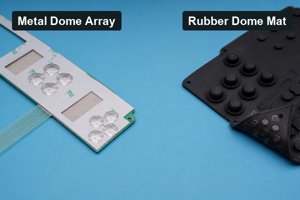
A polydome and metal dome array comparison adds a third option: formed polyester can create a thin tactile element, but its force stability and electrical structure differ from spring stainless steel. The material decision should be verified with the production overlay and actuator, not with loose samples alone.
How Is a Key Dome Used in a Keypad?
A keypad dome switch is built as a stack. From the user side downward, it may include a printed overlay or molded keycap, an actuator layer, a spacer, the dome or dome array, the circuit contact layer and a rigid support. In illuminated controls, a light-guide film or LEDs can be added without interfering with dome travel.
The dome center must align with the visual key center and the actuator. The circuit tail and connector should leave the key field through a controlled route, while adhesive openings around each dome allow movement and venting. Alignment holes or tooling datums should reference both the circuit and the dome carrier.
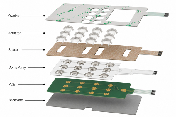
For a rubber dome keyboard, the elastomer mat usually provides both spring action and a guided contact feature. For a metal dome keypad, a PET carrier, spacer or enclosure feature retains the metal parts. Both architectures require stable support beneath the active key area.
Which Dome Shapes and Force Ranges Are Available?
Metal key domes are commonly round, four-leg, triangle or oblong. A round metal dome provides symmetric response when the pad offers a continuous support ring. Four-leg domes provide defined support points and vent sectors. Triangle and oblong geometries fit constrained key layouts but need tighter actuator alignment.
Force must be evaluated together with diameter, travel, click ratio and overlay stiffness. A light dome beneath a thick graphic overlay may feel weak; a heavy dome beneath a small rigid plunger can feel abrupt. EBest Circuit(Best Technology) documents product-dependent options across a broad 100–6000 gf portfolio, but the available range and life target must be confirmed for the selected shape, dimensions and stack.
For multi-key interfaces, force consistency between adjacent positions can matter more than a single nominal number. Carrier thickness, adhesive cutout, PCB support and actuator tolerance should be included in the assembled force study.
How Should the PCB Contact Pattern Be Designed?
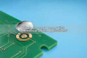
A dome switch PCB normally uses a center contact and an outer contact separated by a controlled gap. The dome perimeter or legs rest on the outer electrode; the crown contacts the center electrode after snap-through. The pad geometry must match the exact dome series and allowed placement tolerance.
Keep soldermask, silkscreen, vias, raised traces and contamination away from the bearing surface. A narrow vent route should connect the cavity beneath the dome to an open volume. The circuit finish should provide stable low-level contact resistance and withstand the cleaning and environmental conditions of the assembly.
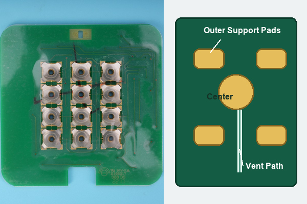
Flexible circuits need a stiffener or rigid backing beneath the switch area. If the FPC bends during actuation, part of the key travel is lost in substrate deflection and the measured force curve no longer represents the dome alone.
What Are the Differences Between Loose Domes and Dome Arrays?
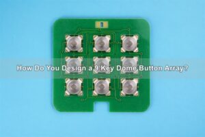
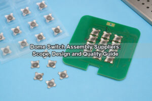
Loose domes minimize carrier material and can suit low key counts, but each part must be oriented, positioned and retained. A custom dome array holds multiple metal domes beneath a registered PET/Mylar carrier. Die-cut openings can control adhesive keepout and venting around every key.
An array reduces placement variation and can arrive as one assembly matched to the PCB or FPC datum scheme. It also allows liners, alignment holes and peel tabs to be designed for the production process. The trade-off is that array tooling and lamination tolerances must be established before volume production.
Single-key peel-and-place pieces sit between the two approaches. They preserve individual placement flexibility while reducing direct handling of the metal surface.
How Do Actuators, Overlays and Plungers Affect Key Feel?
The dome should be pressed near its geometric center by a smooth actuator. A small tip concentrates stress; an oversized tip can touch the fixed perimeter and suppress the snap. Guide clearance must prevent tilt while allowing the key to move without rubbing the housing.
A graphic overlay adds bending stiffness and can distribute force beyond the intended key. A molded keycap can introduce side load if its pivot or guide is not centered. A plunger dome array adds controlled local height when the overlay or enclosure cannot reach the dome directly.
A dome switch button should also include an overtravel stop. Once electrical contact is achieved, additional motion should be limited before the spring is flattened beyond its elastic range. The hard stop belongs in the mechanical stack, not in an assumed finger behavior.
Which Venting and Sealing Rules Matter?
Air beneath a sealed dome must escape during actuation and return during release. Vent channels should avoid adhesive blockage, sharp dead ends and paths that carry dust or liquids directly to the contact. Multiple keys can share a manifold only when the pressure interaction between adjacent keys has been evaluated.
Environmental sealing is normally created above or around the switch cavity rather than by trapping the dome in an airtight pocket. The overlay perimeter, tail exit, housing gasket and adhesive boundaries form the primary barrier. A rubber-glue dome array can add elastomer features to a metal-dome carrier where the stack needs cushioning, local height or sealing support.
Cleaning agents, humidity and temperature can change adhesive flow and rubber modulus. Material compatibility should be tested after aging because an initially open vent can narrow as adhesive creeps.
What Causes Key Dome Problems?
- Uneven feel: actuator height, support stiffness or carrier openings vary between key positions.
- Intermittent contact: pad contamination, adhesive intrusion, oxidation or insufficient center travel prevents stable closure.
- Slow return: a blocked vent or elastomer damping holds the key below its intended release point.
- Permanent deformation: excessive overtravel, off-center load or an undersized actuator overstresses the dome.
- Double actuation: contact bounce, unstable electronics thresholds or cross-coupled membrane traces create repeated signals.
- Key-to-key variation: tolerance accumulation shifts preload and travel across the keypad.
The complete stack should be preserved during analysis. Replacing a damaged dome without checking the actuator, PCB pads, adhesive and backing plate can reproduce the same failure.
How Are Key Domes Tested?
Force-displacement testing records trip force, contact force, return force and travel. An electrical channel should capture the exact closure point, closed resistance and bounce. Dimensional inspection verifies dome height, carrier registration, key pitch and alignment features.
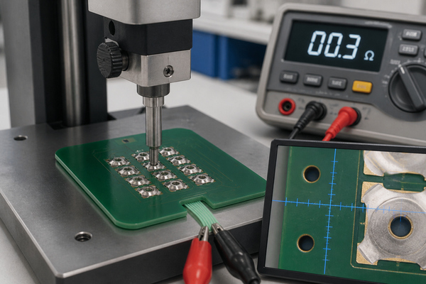
Life testing should reproduce the production actuator, key rate, support and overtravel. Environmental verification can include temperature, humidity, chemical exposure and corrosion conditions appropriate to the application. After testing, compare both electrical resistance and the force curve; a key can continue to switch while losing the required tactile response.
FAQ About Key Domes?
Is a key dome the same as a membrane switch?
No. The dome is one tactile element. A membrane switch is the complete layered interface and may use metal domes, polydomes, embossed keys or no tactile element.
What is the difference between a dome switch and a rubber dome key switch?
A metal dome switch uses spring steel and can directly close PCB contacts. Rubber dome key switches use an elastomer web and commonly a carbon pill or separate conductive feature.
Can a key dome be used directly on a PCB?
Yes, if the pad geometry, surface finish, support, retention and venting are designed for the selected dome. An overlay or carrier is normally used to prevent movement and contamination.
Which key dome is best for a thin keypad?
A metal dome or polydome generally supports a thinner stack than a molded rubber keypad. The final decision depends on travel, sealing, sound, force consistency and tooling requirements.
What does dome switch vs membrane mean?
It usually compares a specific tactile contact mechanism with a complete interface technology. A dome switch can itself be installed inside a membrane keypad, so the two terms are not mutually exclusive.
Conclusion
A key dome should be selected as part of the complete keypad stack. Metal domes favor low profile and crisp snap action; rubber domes favor molded travel, damping and integrated elastomer geometry. In both cases, reliable performance depends on actuator alignment, PCB support, venting, overtravel control and assembled-state testing. For metal dome, dome array or PCB/FPC integration support, contact EBest Circuit(Best Technology) at sales@bestpcbs.com.