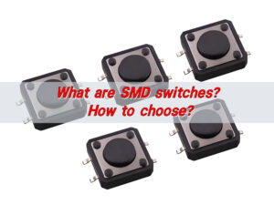
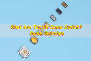
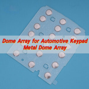
SMT SMD describes two related but different parts of surface-mount electronics: SMT is the manufacturing process, while an SMD is a component designed for that process. The distinction matters when specifying tactile switches because a reflow-solderable SMD metal dome switch is not the same product as a loose dome supplied in carrier tape. Correct selection depends on solderability, pad design, placement method, reflow limits, switch force and the required mechanical stack.
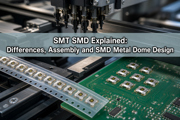
What Does SMT SMD Mean?
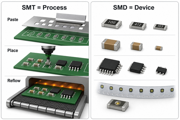
The smt smd meaning becomes clear when the terms are expanded. Surface mount technology is the process used to print solder paste, place components on PCB pads, reflow the solder and inspect the assembled board. A surface mount device is the resistor, capacitor, IC, connector, switch or other package placed by that process.
An SMD is therefore a physical item; SMT is the production method. A component can be supplied in tape-and-reel packaging but still require verification that its terminals, polymer films and internal contacts can tolerate the specified reflow profile. Packaging alone does not make a loose metal dome solderable.
What Is the Difference Between SMT and SMD?
The shortest answer to smt vs smd is process versus product. The smt smd difference affects drawings, bills of materials and assembly instructions: the BOM identifies the SMD package and part number, while the manufacturing data defines paste, pad, placement, reflow and inspection requirements.
| Item | SMT | SMD |
|---|---|---|
| Meaning | Surface-mount assembly technology | A component made for surface mounting |
| Controlled by | Stencil, printer, placement machine, oven and inspection plan | Package drawing, terminal finish, ratings and storage requirements |
| Typical output | A populated and soldered circuit board | A resistor, IC, LED, connector or tactile switch package |
| Main risk | Paste, placement, thermal-profile or inspection error | Wrong package, polarity, coplanarity or reflow compatibility |
How Does the SMT Assembly Process Work?
SMT assembly normally starts with stencil printing. Solder paste is deposited onto selected pads, a placement machine picks components from reels or trays, and the board passes through a controlled reflow profile. The solder joints are then inspected using optical, X-ray or electrical methods appropriate to the package.
- Verify PCB finish, pad geometry, stencil apertures and moisture controls.
- Print solder paste and check volume, alignment and bridging risk.
- Pick each SMD from its feeder and place it within the package tolerance.
- Run the approved preheat, soak, peak and cooling profile.
- Inspect polarity, solder fillets, opens, shorts, tombstoning and package damage.
The profile must follow the most temperature-sensitive package in the assembly, not a generic oven setting. For a tactile switch, excessive heat or dwell can affect film, adhesive, actuator geometry or switch force even when the solder joints appear acceptable.
Which SMD Components Are Common on a PCB?
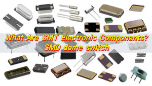
Common SMD components include chip resistors, an SMD capacitor, diodes, LEDs, transistors, integrated circuits, connectors, sensors and switches. Their package formats determine feeder selection, nozzle geometry, polarity controls, inspection access and rework strategy.
Passive chips may use simple rectangular pads, while fine-pitch ICs need tighter paste and placement control. A tactile switch adds a mechanical output requirement: the assembled device must not only conduct but also deliver the specified trip force, travel, click ratio and return behavior after reflow.
What Is an SMD Metal Dome Switch?
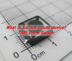
An SMD dome switch is a packaged tactile contact designed for direct surface mounting and reflow soldering. The package combines circuit terminals, a formed metal dome, protective polyimide film and, on applicable models, a center actuator. Pressing the actuator snaps the dome onto the internal contact; releasing it lets the dome recover and reopen the circuit.
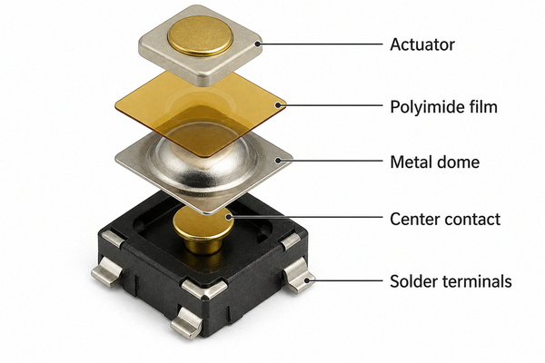
The SMD metal dome product range includes compact formats for constrained layouts. EBest Circuit(Best Technology) publishes a 3.4 × 3.0 × 0.7 mm example and a rated life of at least 100,000 operations for the applicable SMD dome family; final values must be confirmed against the selected part-number drawing.
How Does Pick-and-Place Handle SMD Dome Switches?
An SMD machine feeds the switch from continuous carrier tape, presents each pocket at a controlled pickup point and places the package on pasted PCB pads. The nozzle must contact a stable top surface without depressing or shifting the actuator. Feeder pitch, tape width, pocket orientation and pickup height must match the released packaging specification.
Placement programming should include the correct centroid, rotation, nozzle and force. Excessive placement force can preload the dome; insufficient force can leave terminals outside the paste deposit. A first-article run should confirm package seating before reflow and tactile operation after cooling.
SMD Metal Dome vs Tape-and-Reel Loose Dome vs Dome Array?
These products solve different assembly problems. Select them by electrical attachment, placement method and stack integration rather than by the fact that all three may arrive in an organized carrier.
| Option | Attachment | Best fit | Critical limitation |
|---|---|---|---|
| SMD metal dome switch | Reflow-soldered terminals | Automated PCB assembly with a packaged tactile switch | Must follow the part-specific pad and reflow specification |
| Tape-and-reel loose metal dome | Mechanically retained after placement | Automated positioning of a conventional snap dome | The loose dome itself is not soldered |
| Custom dome array | Adhesive PET/Mylar carrier | Multiple keys, coordinated alignment, venting or overlay integration | Lamination and carrier stack must be controlled |
Which PCB Pad and Reflow Factors Matter?
The PCB footprint must come from the selected switch drawing. Pad length, width, spacing and solder-mask clearance affect wetting, alignment and bridging. Stencil apertures control paste volume; too little paste can create opens, while excess paste can float or tilt a small package. Copper imbalance around the switch can also produce asymmetric heating.
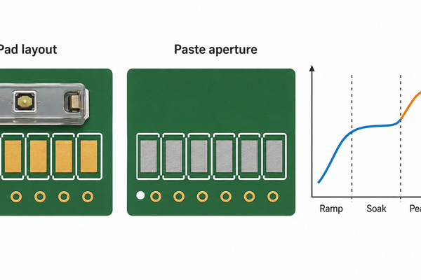
The reflow profile should control ramp rate, soak, peak temperature, time above liquidus and cooling. Validate switch force and continuity after the actual board has passed through the intended oven. A successful solder joint does not by itself prove that the actuator film, dome geometry and contact behavior remain within specification.
When Should SMD Be Chosen Instead of THT?
Choose SMD when board area, automated placement, short interconnects and double-sided population are priorities. Choose through-hole when the component needs strong lead anchoring, unusual power handling or mechanical retention that the surface pads cannot provide. For readers comparing SMD vs SMT vs THT, remember that SMT is the process, while SMD and THT describe component mounting formats.
The SMD vs through hole decision should be made at component level, not for the entire board. A PCB can combine surface-mounted electronics with through-hole connectors or switches when each technology matches its mechanical and electrical load.
What Causes SMT SMD Assembly Defects?
Typical causes include incorrect paste volume, feeder rotation errors, poor package coplanarity, contaminated pads, unsuitable thermal profiles and inspection criteria that check solder but ignore switch mechanics. Tactile packages also fail when a nozzle presses the actuator, when the package is placed off-center or when cleaning chemistry enters an unsealed structure.
- Use the released land pattern and package orientation marker.
- Inspect solder-paste deposits before placement.
- Confirm nozzle contact area and placement force on trial boards.
- Record the real board temperature at the switch location during profiling.
- Test electrical closure, trip force and return after reflow and cleaning.
These controls address smt smd soldering as a combined assembly problem instead of treating every defect as a component fault.
How Are SMD Dome Switches Tested?
Testing should combine dimensional, solderability, electrical and tactile checks. Incoming inspection verifies package size, terminal condition and tape orientation. Process validation checks pickup, placement, reflow and board cleanliness. Finished-board testing confirms open-state insulation, closed-state resistance, operating force, travel, return and cycle durability.
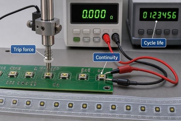
EBest Circuit(Best Technology) publishes trip-force, rebound-force, life-cycle, electrical-performance and dimensional testing capabilities for metal dome products. Test limits must be tied to the selected model and the assembled board condition because the PCB, solder joint and actuator can influence the measured response.
FAQ About SMT SMD?
What Is SMT vs SMD?
SMT is the surface-mount production process; SMD is a component designed to be placed and soldered by that process.
What Does SMT Stand for?
SMT stands for Surface Mount Technology.
What Does SMD Stand for?
SMD stands for Surface Mount Device.
What Does SMT Stand for in Electronics?
In electronics, SMT identifies the workflow used to print paste, place surface-mount packages and reflow them on PCB pads.
What Is SMD in Electronics?
An SMD is an electronic component with terminals or contacts intended for mounting directly on the PCB surface.
What Is SMT in Semiconductor?
In semiconductor assembly discussions, SMT usually refers to mounting packaged semiconductor devices onto a circuit board; it is distinct from wafer fabrication and internal chip packaging.
Conclusion
SMT SMD should be specified as a process-and-package pair: the assembly line controls solder paste, placement and reflow, while the selected device controls footprint, ratings and mechanical behavior. For tactile controls, confirm whether the project needs a reflow-solderable SMD dome switch, a mechanically retained loose dome or an adhesive dome array. Use the released part drawing and validate the complete board after reflow.
For model selection, package drawings and application review, contact EBest Circuit(Best Technology) through the Metal Dome contact page.