Metal dome array installation is the controlled process of cleaning the PCB or FPC, aligning a pre-positioned dome sheet with its contact pads, laminating the pressure-sensitive adhesive without preloading the domes, and verifying every key electrically and mechanically. Reliable installation depends on the complete switch stack, not only on placing the PET carrier over the board.
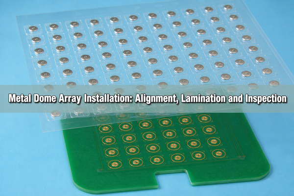
The installation plan should define the array construction, contact surface, alignment datums, release-liner sequence, lamination pressure, vent routes, handling time and acceptance checks before production begins. These controls prevent a sheet that looks correctly attached from developing intermittent contact, uneven click feel, edge lift or trapped-air defects.

What Is Included in a Metal Dome Array Installation Stack?
A typical installation stack includes a PET or Mylar carrier, pressure-sensitive adhesive, metal domes, optional spacer, release liner, PCB or FPC contact layer, and any overlay or actuator installed above the array. Each layer changes the final height, dome clearance and force path.
The carrier keeps the domes at their drawing positions while the adhesive bonds to the circuit surface. A single-layer array holds the domes directly under one adhesive carrier. A double-layer array adds a spacer beneath the dome layer to create controlled cavities and air paths. Plungers, rubber glue or an LGF can be added above the basic stack when the keypad needs additional height, sealing or illumination.
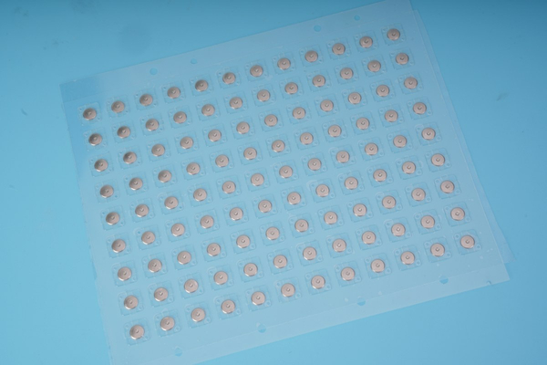
The metal dome array product range shows the available sheet structures. The installation drawing must identify which surface actually receives the adhesive and whether the board, spacer or housing supplies the dome cavity. Treating every dome sheet as the same construction can create insufficient clearance or an unintended air seal.
What Must Be Checked Before Metal Dome Array Installation?
Before removing the release liner, confirm that the dome locations, array outline, orientation feature, tooling holes and PCB pads match the approved drawing. A dry fit with the liner still attached reveals rotated arrays, mirrored artwork, incorrect hole spacing and board-outline conflicts without exposing the adhesive.
- Verify the array part number, revision and dome orientation.
- Check PCB flatness and inspect for bow, contamination or damaged solder mask.
- Confirm that every center pad is electrically isolated from its outer contact.
- Check tooling holes, edge datums and asymmetric features for correct orientation.
- Inspect the carrier for creases, shifted domes, damaged cavities or liner lift.
- Confirm that vents, cutouts and component keep-outs remain open.
Store the array flat until use. Curling the sheet, stacking heavy objects on the domes or partially separating the liner can move domes or contaminate the bond surface before installation starts.
How Should the PCB or FPC Surface Be Prepared?
The mounting surface must be clean, dry, flat and compatible with the selected adhesive. Dust can hold a dome above its pad, while oil, flux residue, silicone contamination or fingerprints can reduce local bond strength. Oxidized or damaged contact pads can cause electrical failure even when the array is perfectly aligned.
Use a residue-free cleaning method approved for the board finish and nearby components. A lint-free wipe with suitable isopropyl alcohol is common, but the concentration, wipe material and drying procedure should follow the assembly specification. Do not flood unsealed components or assume every coating is compatible with the cleaner.
Inspect the cleaned area under adequate lighting or magnification. Installation should not begin while solvent remains in vias, cutouts or under components. For FPC, support the flex on a flat fixture so the film cannot stretch or wrinkle during lamination.
Which Placement Method Should Be Used?
The placement method should match the array size, alignment tolerance, board geometry and production volume. Visual placement can be sufficient for a simple prototype with generous datums. A fixture is more repeatable for regular production, while automated handling can reduce cycle time for suitable sheet or panel formats.
| Method | Best fit | Main control | Typical limitation |
|---|---|---|---|
| Visual alignment | Prototype or very small quantity | Clear marks and operator magnification | Operator-dependent position variation |
| Application fixture | Repeated manual production | Guide pins, PCB edge stops and poka-yoke orientation | Dedicated tooling is required |
| Automated placement | Stable higher-volume process | Machine datum, vacuum handling and programmed pressure | Requires equipment-compatible carrier and panel design |
For peel-and-place handling, the peel-and-place metal dome format allows multiple domes to be positioned as one registered sheet. Loose-dome placement is a different process and carries a greater risk of wrong orientation or double domes when handled manually.
How Is a Metal Dome Array Installed Step by Step?
A controlled installation sequence exposes as little adhesive as practical, establishes alignment before full contact, and laminates from the registered area outward. The exact liner-peel direction and pressure tool should be documented for the selected array.
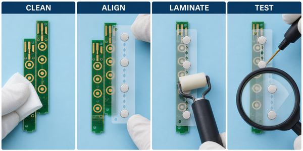
- Clean and inspect. Remove particles and residue, allow the surface to dry, and confirm the pads and board are acceptable.
- Dry-align the array. Verify orientation, tooling holes, board edges and dome-to-pad registration before exposing adhesive.
- Remove the liner without touching adhesive. Hold the sheet at nonfunctional edges or use clean tooling. For a large array, a staged liner removal can reduce uncontrolled contact.
- Register the first datum. Engage guide pins or an edge stop and lightly tack a defined bond area. Recheck position before continuing.
- Laminate progressively. Use a clean soft roller or specified flat tool to press adhesive lands from the registered area toward the outer edge.
- Protect dome movement. Do not apply concentrated load to dome crowns and do not stretch the PET carrier across cavities.
- Condition the bond. Keep the installed array flat and free from mechanical disturbance for the adhesive dwell period defined by its datasheet.
- Inspect and test. Check alignment, edge bonding, vents, continuity, return behavior and tactile consistency before adding the final overlay or enclosure.
For a shorter handling overview, see the existing basic metal dome array installation article. The sequence above adds the production controls needed for repeatable assembly.
How Should Alignment Features Be Designed?
Alignment features should constrain the array in X, Y and rotation without stretching the carrier. Tooling holes, PCB edges, notches and asymmetric outlines are more reliable than visual dome-to-pad alignment alone. The datum scheme should be shared by the array artwork, PCB fabrication drawing and installation fixture.
Guide pins need enough clearance to load the sheet without tearing the PET, but excessive clearance reduces placement accuracy. Edge stops should reference stable PCB features rather than routed edges with large tolerance. If a board has no usable holes, the fixture can combine two perpendicular edge stops with one orientation feature.
EBest Circuit(Best Technology) can review AutoCAD, PDF, Gerber, PCB, CAM and other PCB files for a custom dome array. Published dome-array dimensional tolerance is approximately +/-0.05 to +/-0.15 mm depending on the construction, so the drawing must assign tolerances to dome locations, carrier outline and tooling features rather than relying on a general note.
How Should Pressure Be Applied Without Preloading the Domes?
Lamination pressure should act on adhesive bond lands, not as a concentrated force on the dome crown. Pressing the carrier too tightly across a cavity can apply a constant load to the dome. This pre-load reduces free travel, changes trip force and click ratio, and may keep the dome from returning consistently.
Start at the registered bond area and move outward in a controlled path. A soft roller can distribute pressure across wider lands, but the roller diameter and hardness must suit the dome height and key pitch. A hard narrow roller can bridge poorly or push directly over dome peaks.
Do not use maximum manual force as a substitute for correct adhesive selection. If edges lift after normal lamination, check surface compatibility, contamination, adhesive thickness, bond-land width and dwell conditions before increasing pressure.
Why Must Venting Remain Open During Installation?
Venting allows air to leave and re-enter each dome cavity during actuation. If installation seals or blocks the intended air path, trapped air can hold the dome against the carrier instead of allowing it to rest on the circuit surface. This floating condition can change tactile response and contact reliability.
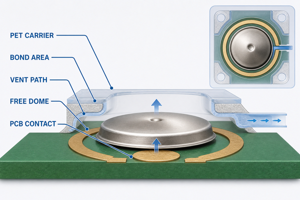
During progressive lamination, press around the dome edge and move air toward the designed vent route. Never cover a vent with an added label, adhesive patch or housing rib without reviewing the airflow. Shared channels in a multi-key array must remain continuous after die cutting and bonding.
The existing metal dome venting guide explains cavity air paths in more detail. Venting must be checked together with adhesive windows and bond lands because each feature uses the same limited area around the dome.
How Do Single-Layer and Double-Layer Arrays Change Installation?
A single-layer array relies on the adhesive carrier and the receiving surface to provide the required dome clearance. Installation therefore depends heavily on the PCB pad area, solder-mask relief and any cavity provided by the product structure. The sheet should lie flat without pulling tightly over the dome crown.
A double-layer dome array adds a spacer with defined openings and air paths. The spacer can protect the dome edge and control cavity height, but it also introduces another die-cut layer whose vents and bond lands must align with the PCB. The assembly fixture should reference the complete laminated outline, not only the top PET layer.
Single-layer and double-layer arrays should not share an installation work instruction unless their liner sequence, thickness and pressure path are genuinely identical. The single-layer dome array remains useful for thin, straightforward stacks, while a double-layer structure is preferable when controlled cavities and routed vent paths are needed.
What Installation Defects Change Tactile Feel or Contact?
Installation defects often appear first as one key that feels different from adjacent keys. The location and pattern of the symptom help separate an isolated particle or shifted dome from a broader pressure, material or alignment problem.
| Observed defect | Likely installation cause | Check |
|---|---|---|
| Intermittent electrical contact | Contaminated pad, off-center dome or incomplete seating | Inspect pad, dome center and continuity during controlled actuation |
| Heavy or muted click | Carrier pre-load, blocked vent or overlay interference | Compare force curve before and after full stack assembly |
| Slow return | Restricted air path or damaged dome | Inspect vent continuity and dome profile |
| Edge lift | Poor cleaning, low surface compatibility or insufficient bond area | Review surface, adhesive and local peel direction |
| Key-to-key variation | Uneven lamination, board bow or fixture error | Map position error and tactile data across the complete array |
Do not repair a damaged key by pressing harder on the dome. Remove the assembly according to the approved rework process, inspect the board, and replace the array when the carrier, adhesive or dome has been compromised.
How Should the Installed Array Be Inspected and Tested?
Final acceptance should combine visual, electrical and tactile checks. A visual pass alone cannot confirm contact resistance or dome return, while continuity alone cannot reveal edge lift, blocked vents or a gradually changing click ratio.
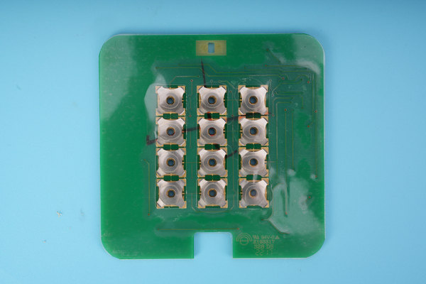
- Visual: verify orientation, dome centering, carrier flatness, edge bonding, vent openings and absence of particles or bubbles.
- Electrical: confirm open state at rest, closed state during actuation and stable continuity for every key.
- Tactile: compare trip force, return, click response and key-to-key consistency with the approved sample or specification.
- Dimensional: measure array-to-board registration at defined datums instead of judging position only by appearance.
- Environmental: when required, repeat functional checks after the specified temperature, humidity or aging exposure.
EBest Circuit(Best Technology) lists curve testers, electric testers and precision dimensional measurement equipment among its production resources. These tools support installation validation when the acceptance criteria define measurable force, electrical and positional limits.
FAQ About Metal Dome Array Installation
Can a Metal Dome Array Be Removed and Reinstalled?
Reusing the same array is not recommended. Removal can stretch the PET, contaminate or weaken the adhesive, shift domes and alter the cavity. If rework is necessary, clean and inspect the board before installing a new array.
Can Standard Metal Domes Be Soldered to the PCB?
Standard snap domes are normally retained by an array, tape or spacer pocket rather than soldered. Solder can restrict the edge movement needed for snap action. Only a dome specifically designed as a solderable SMD part should enter an SMT soldering process.
When Should Electrical Testing Be Performed?
Run an initial continuity and tactile check after installation, then repeat it after the adhesive conditioning period and after the remaining overlay or actuator layers are assembled. The final stack can change force transfer and dome return.
When Is an Installation Fixture Necessary?
A fixture is appropriate when visual alignment cannot repeatedly hold the drawing tolerance, when the array has many keys, or when production volume makes operator variation costly. The fixture should use stable PCB datums and prevent reversed loading.
Should Pressure Be Applied Directly Over Each Dome?
No. Apply controlled pressure to the adhesive bond lands and work outward along the specified lamination path. Concentrated force on the crown can pre-actuate or damage a dome and can hide a venting or clearance problem.
Conclusion
Reliable metal dome array installation combines clean contact surfaces, positive alignment datums, controlled liner removal, progressive lamination, open vent paths and measurable inspection. The array construction and fixture must be designed together so the adhesive holds every dome in position without restricting snap movement.
For a custom installation stack, send the PCB or FPC drawing, dome positions, array outline, tooling features, layer construction and test requirements through the Metal-Domes contact page. EBest Circuit(Best Technology) can review the array structure and alignment features before prototype assembly.