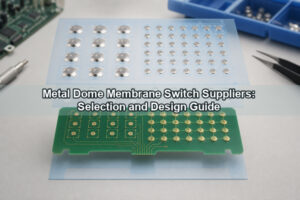
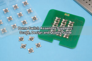
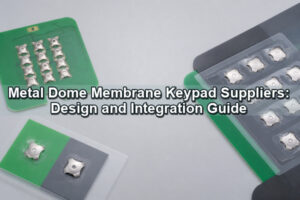
Dome array adhesive selection determines whether a PET carrier remains bonded, each metal dome stays centered, trapped air can escape and the assembled key preserves its intended snap response. A suitable pressure-sensitive adhesive must match the actual mounting surface, operating environment, bond geometry and lamination process. Selecting only by brand or initial tack can leave the array vulnerable to edge lift, preload, contamination or tactile drift.

The practical sequence is to define the substrate and exposure conditions first, choose the adhesive family second, and then design the carrier thickness, adhesive windows, vent paths and bond lands around that material. The final choice is confirmed on the production surface and in the complete switch stack, not on a generic laboratory panel alone.
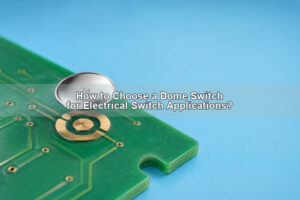
Why Does Dome Array Adhesive Selection Matter?
The adhesive does more than attach a sheet to a PCB. It locates every snap dome over its contact pads, seals the perimeter of each cavity, supports handling during assembly and transfers local stresses into the PET carrier. These functions must be achieved without pulling the carrier tightly against the dome crown or obstructing the dome edge.
A strong bond can still produce a poor switch if the adhesive layer is too thick, the cavity is too small or the carrier is too stiff. Conversely, a mechanically correct cavity can fail if cleaning residue, a low-surface-energy plastic or repeated humidity exposure weakens the bond. The adhesive family and die-cut geometry therefore need to be treated as one design.
For a broad introduction to sheet construction and peel-and-place installation, see the existing adhesive dome array guide. This article concentrates on material selection and reliability boundaries.
How Is a Dome Array Adhesive Stack Constructed?
A common dome array uses a continuous polyester carrier above the metal domes, a die-cut PSA bond layer around the active cavities and a removable liner that protects the adhesive before placement. A double-layer construction adds a spacer beneath the dome carrier so that vent paths and cavity height can be controlled independently.

Each layer has a separate job. The PET carrier controls registration and handling. The PSA provides the bond land. The dome creates the electrical and tactile action. The spacer establishes free movement and airflow. The release liner protects the adhesive and preserves dimensional stability during die cutting, shipping and placement.
The carrier is not a substitute for the spacer. If a dome needs more free height or a dedicated air path, increasing adhesive thickness alone can create a soft, unstable bond line rather than a controlled cavity. The stack should be dimensioned from the PCB surface to the top actuator so that every layer has a defined thickness and tolerance.
Which Specifications Should Be Fixed Before Adhesive Selection?
Adhesive selection should begin only after the mating surface, service environment and switch geometry are defined. Otherwise, a tape that bonds well to a clean test coupon may be unsuitable for the actual solder mask, molded plastic, silicone keymat or coated metal support.
- Identify every bonded surface by material, coating, texture and expected cleanliness.
- Define the continuous and short-term temperature exposure at the adhesive joint.
- List humidity, condensation, cleaning fluids, skin oils, lubricants and UV exposure that can reach the bond.
- Record dome diameter, free height, pitch, orientation and the required venting method.
- Define PET carrier thickness, spacer thickness, adhesive thickness and total stack tolerance.
- Choose the placement method, alignment datums, lamination pressure and acceptable rework method.
The drawing should also show perimeter cuts, windows, slots, component keep-outs and any area where the adhesive must not contact the dome. A custom dome array can incorporate these features into one registered sheet instead of relying on separate manual placement steps.
When Should Acrylic, Rubber-Based or Silicone PSA Be Used?
Acrylic pressure-sensitive adhesive is the usual starting point for a dome array because many grades combine stable aging, useful chemical resistance and clean die-cut processing. Rubber-based PSA is considered when rapid wet-out and high initial tack are important, while silicone PSA is reserved for silicone rubber, extremely low-surface-energy materials or temperature conditions that a selected acrylic grade cannot meet.

| Adhesive family | Useful starting conditions | Main limits to verify |
|---|---|---|
| Acrylic PSA | Smooth PCB surfaces, PET, PC, ABS, metals and general industrial assemblies | Initial wet-out on textured or low-energy surfaces; exact chemical and temperature rating |
| Rubber-based PSA | Applications needing fast initial tack on compatible clean surfaces | Long-term aging, heat, UV, plasticizer and solvent resistance |
| Silicone PSA | Silicone rubber, silicone foam, difficult low-energy surfaces or specialized heat exposure | Higher material and processing complexity, liner compatibility and residue control |
These categories are not interchangeable specifications. Two acrylic PSA products can have different thicknesses, carriers, liners, surface-energy ranges and environmental ratings. The exact product datasheet and representative-surface testing remain decisive. Metal-Domes can provide rubber glue metal dome arrays using silicone or acrylic PSA structures when the application requires an additional top adhesive layer.
What Is the Difference Between Acrylic and Rubber Adhesive?
The main difference between acrylic and rubber adhesive is the balance between immediate tack and long-term environmental stability. Rubber-based systems often wet out quickly and develop useful initial adhesion with limited dwell. Acrylic systems commonly build adhesion over time and are available in grades designed for improved resistance to heat, humidity, UV and chemicals.
That distinction does not make acrylic automatically better. A lightly loaded indoor assembly may perform well with a qualified rubber-based adhesive, while a rough or contaminated surface can defeat an acrylic PSA chosen only for its published durability. Conversely, using a high-tack rubber adhesive in a warm, chemically exposed enclosure without aging tests can produce creep, residue or edge lift.
The comparison should use the same PET thickness, bond area, surface preparation, lamination pressure and conditioning time. Otherwise, a change in carrier stiffness or processing can be mistaken for a difference between adhesive chemistries.
How Does Surface Energy Change Adhesive Choice?
Surface energy controls how easily a PSA wets the mating surface. Clean metals, glass and some rigid polymers generally allow easier wet-out than polyethylene, polypropylene, silicone rubber or surfaces containing mold release. Solder mask, conformal coating, ink, plating and plastic additives can also change the effective surface presented to the adhesive.
Do not classify a PCB simply as “FR4.” The adhesive normally contacts solder mask, legend ink, a plated region or a protective coating rather than bare laminate. A flex circuit may present polyimide coverlay, PET or an adhesive cover film. Each finish should be tested as processed, including the normal cleaning and storage history.
Surface texture matters with surface energy. A thin transfer adhesive may bridge over deep texture and touch only the high points, reducing effective bond area. A more conformable construction can improve contact, but extra thickness near the dome must not restrict snap travel. Surface treatment or a compatible primer may be preferable to simply selecting a thicker tape.
How Do Temperature, Humidity, Chemicals and UV Affect Selection?
Environmental exposure changes both adhesive strength and the mechanical behavior of the carrier. Heat can soften a bond line and increase creep. Cold can reduce tack and flexibility. Humidity can enter through edges or vent routes. Cleaning agents, oils and plasticizers can swell, soften or contaminate the adhesive. UV exposure can degrade materials near transparent overlays.
Separate normal operating conditions from short assembly or storage excursions. A brief process peak is not equivalent to continuous service at the same temperature. Likewise, a material that survives dry heat may respond differently when heat and humidity occur together.
Test the complete stack after realistic exposure. The useful checks are not limited to whether the sheet remains attached. Measure edge lift, dimensional change, tactile force, return behavior, electrical continuity and visible adhesive migration. Any cleaning-fluid test should use the actual concentration, wipe method and exposure duration expected in the product.
How Do Adhesive Thickness and Carrier Stiffness Affect Tactile Feel?
Adhesive thickness and carrier stiffness affect how freely the dome can collapse and return. A thick or highly conformable bond line can move under repeated loading. A stiff top film can bridge between bond lands and press on the dome crown. A cavity that is too shallow can preload the dome before the actuator touches it.
Preload typically appears as increased actuation force, reduced click ratio, incomplete return or a key that feels different after lamination. The same symptoms can come from a small adhesive window, trapped air or an off-center actuator, so the stack should be diagnosed layer by layer.
Thickness changes should be evaluated with force-displacement curves before and after assembly. Measure the loose dome first, then the dome under the PET carrier, and finally the complete key with overlay or plunger. This separates the contribution of the dome from the contribution of the adhesive stack.
How Much Bond Area Is Needed Around Each Dome?
There is no universal bond-land width for every dome array. The required area depends on dome diameter and height, key pitch, adhesive family, carrier stiffness, surface texture, vent-channel geometry, perimeter cuts and die-cut tolerance. The land must be wide enough to resist peel and seal the cavity without entering the dome’s moving region.
Closely spaced keys create competing requirements. Narrow lands save panel area but reduce peel resistance and leave less room for vent paths. Large lands improve bonding but can make routing and component clearances difficult. Where keys sit near an outer edge, screw boss or display window, the local bond geometry may need to be enlarged or supported by a spacer.
Use the adhesive supplier’s test method to establish peel or shear performance on the actual surface, then confirm the local geometry in a finished keypad. Coupon values cannot represent stress concentration at a die-cut corner or a vent-channel intersection.
How Should Vent Channels and Adhesive Windows Be Designed?
Adhesive windows must leave the dome crown and moving edge free, while vent channels must let cavity air move without cutting the bond land into weak islands. The vent route can connect each cavity to a protected internal volume or link selected cavities through a spacer network.

A channel that is clear in the CAD file may narrow after lamination if the adhesive flows or the spacer compresses. It should avoid the electrical contact area, remain separated from contamination paths and preserve enough land between the channel and every through-cut. More detail on cavity airflow is available in the metal dome venting guide.
Inspect first articles under transmitted light to confirm the windows, vents and domes remain registered after die cutting and lamination. Functional pressing should then verify that adjacent keys do not influence one another through shared air paths.
When Is a Single-Layer or Double-Layer Dome Array Better?
A single-layer array is appropriate when the top adhesive carrier can hold the domes, the PCB or flex circuit provides adequate cavity relief and venting can be achieved without a separate spacer. A double-layer array is better when the design needs a controlled spacer cavity, routed air paths or additional protection from dome-edge contact with the carrier.
| Decision point | Single-layer array | Double-layer array |
|---|---|---|
| Stack height | Thinner and simpler | Higher but more controllable |
| Venting | Vent holes or board features may be required | Spacer can contain routed air paths |
| Dome clearance | Depends heavily on carrier window and board relief | Spacer establishes a dedicated cavity |
| Die-cut complexity | Lower | Higher because layers must remain registered |
| Use case | Compact layouts with proven clearance | Layouts needing controlled venting or added isolation |
Review the single-layer dome array and double-layer dome array structures as mechanical alternatives. The selection should follow the required cavity and vent design rather than a preference for the lowest layer count.
How Do Release Liners and Lamination Conditions Affect Assembly?
The release liner protects the PSA and keeps the die-cut array flat until placement. Its stiffness, release level and cut pattern influence whether small adhesive features remain on the carrier during peeling. A liner that releases too easily can shift parts in handling, while an aggressive liner can stretch the carrier or lift narrow bond features.
Before lamination, remove dust, oil and cleaning residue without touching the exposed adhesive. Align the array from defined datums rather than from the flexible outer edge. Apply pressure uniformly from the center or registered start point toward the perimeter so air is displaced instead of trapped around the domes.
Conditioning time also matters because many PSAs build adhesion after application. Functional testing can begin immediately for alignment checks, but environmental and peel comparisons should follow the conditioning procedure in the adhesive datasheet. Keep lamination pressure, roller hardness, speed and temperature consistent between prototypes and production.
What Failure Modes Reveal a Poor Adhesive Match?
Adhesive-related failures often appear as mechanical or tactile symptoms before the sheet separates completely. Recording the location and timing of each symptom helps distinguish a material mismatch from a die-cut or assembly problem.
| Observed condition | Likely mechanism to investigate | Useful confirmation |
|---|---|---|
| Edge lift | Low wet-out, contamination, insufficient land or peel stress | Surface inspection and peel test on the processed substrate |
| Bubbles near domes | Trapped air, inadequate venting or uneven lamination pressure | Transmitted-light inspection and controlled relamination trial |
| High or inconsistent force | Carrier preload, small adhesive window, off-center actuator or blocked vent | Force-displacement comparison at each assembly stage |
| Slow return or sticking | Adhesive migration, cavity interference or softened bond line | Heat exposure followed by visual and tactile inspection |
| Array shift | Low shear resistance, creep or insufficient dwell before loading | Shear test and dimensional measurement after conditioning |
| Residue during rework | Adhesive/substrate incompatibility or excessive heat during removal | Controlled removal trial on the final surface finish |
A single symptom can have more than one cause. Replacing the tape without checking window geometry, venting and actuator alignment can reproduce the same failure with a different adhesive.
How Should Dome Array Adhesive Performance Be Validated?
Validation should use the final substrate, surface preparation, dome geometry, carrier, spacer, liner and lamination process. Tests on bare metal or glass are useful for material screening but cannot qualify an array that will be mounted on textured solder mask or plastic.

- Inspect registration, adhesive windows, vent routes, perimeter lands and visible bubbles.
- Measure peel or shear behavior after the specified dwell on the processed mounting surface.
- Record force-displacement and electrical continuity before and after lamination.
- Cycle representative center and edge keys with the intended actuator and backing support.
- Repeat adhesion, tactile and dimensional checks after heat, cold, humidity and chemical exposure.
- Verify removal behavior when the product requires service or controlled rework.
Acceptance limits should be tied to the finished switch function. A sheet can pass a peel requirement and still fail because the carrier preloads the dome. It can also preserve tactile force while edge lift creates a contamination path. Both bond integrity and switch performance must remain within the approved specification.
What Design Inputs Control a Custom Dome Array Adhesive?
The controlling inputs are the PCB or FPC artwork, array outline, dome part and orientation, mating surface, layer stack, venting method, alignment datums and environmental test conditions. These items allow the adhesive family and die-cut geometry to be evaluated together.
EBest Circuit(Best Technology) has manufactured metal domes and metal dome arrays since 2006. Its published dome-array capability includes polyester carriers, silicone or acrylic PSA options for rubber-glue structures, and King Label, 3M 467 or 3M 468 adhesive options for applicable single-key and plunger arrays. Material selection remains subject to the actual surface, stack and environment.
Custom array review can use AutoCAD, PDF, Gerber, PCB, CAM or other PCB files. The technical drawing should identify dome locations, cutouts, tooling features and layer relationships clearly enough to check whether the adhesive window, vent route and bond land can be manufactured without restricting dome movement.
FAQ About Dome Array Adhesive Selection
Can Standard Double-Sided Tape Be Used for a Dome Array?
Only when its adhesive chemistry, thickness, liner, die-cut behavior and environmental rating have been qualified for the exact surface and stack. General-purpose mounting tape may bond to the board but remain too thick, too soft or too difficult to die cut around the domes.
Does Adhesive Thickness Change Metal Dome Actuation Force?
It can. Thickness changes the cavity, bond-line compliance and carrier position. If the layer presses the PET against the dome or narrows the free space, actuation force can rise and click ratio can fall. Confirm the effect with force-displacement measurements on the laminated switch.
Can One PSA Bond to FR4, FPC and Silicone Rubber?
Do not assume one PSA will perform equally on all three. The actual contacts may be solder mask, polyimide, PET, coating or silicone rubber, and these surfaces have different energy, texture and contamination risks. A silicone-compatible PSA may be needed for silicone rubber, while a qualified acrylic can be suitable for many PCB and flex-circuit surfaces.
Is 3M Adhesive Required for Every Metal Dome Array?
No. A specified 3M product can provide traceable construction and datasheet information, but another qualified adhesive may meet the same functional requirements. Selection should be based on surface compatibility, thickness, environment, processing and validation rather than brand alone.
When Should Adhesion Be Tested After Lamination?
Immediate checks are useful for placement and tactile function, while final peel, shear and environmental comparisons should follow the adhesive manufacturer’s conditioning procedure. The same dwell, pressure and temperature should be used for every compared sample.
Conclusion
Reliable dome array adhesive selection begins with the real mounting surface and service environment, then coordinates PSA chemistry with PET thickness, adhesive windows, bond lands, venting and lamination. Acrylic is a practical starting family for many arrays, but rubber-based or silicone PSA may be appropriate when initial tack, difficult surfaces or specialized exposure changes the requirement.
EBest Circuit(Best Technology) supports custom single-layer, double-layer and rubber-glue dome-array structures with material and stack review. For technical support, contact sales@metal-domes.com.