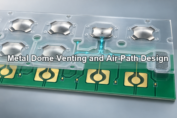
Metal dome venting is not just a hole near a snap dome. It is a complete air path from the dome cavity, through a controlled channel, to an endpoint that remains open after lamination and final assembly. The design must let displaced air move during press and release without weakening adhesive support, crossing the electrical contact area, or creating a direct contamination path.
What Should Metal Dome Venting Control in the Finished Switch?
A vent design should control the pressure change inside each dome cavity without becoming another failure path. The finished switch, not the loose dome, is the correct design boundary. Overlay stiffness, actuator geometry, PET retention, adhesive thickness, PCB support and enclosure compression all influence whether the planned path remains usable.
Define four elements before choosing a vent shape: the dome cavity, the channel entry, the route through the spacer or another permitted layer, and the endpoint. A line that stops inside adhesive is not a complete route. An edge opening that bypasses a product seal may move air but still fail the environmental requirement.
- The cavity must allow the dome to collapse and recover without rubbing the spacer.
- The entry must remain open beside the dome while avoiding the contact zone.
- The route must survive die cutting, adhesive flow and lamination pressure.
- The endpoint must exchange air with a permitted volume: atmosphere, a PCB vent, another cavity or a protected internal reservoir.
Where Does Air Move During Press and Release?
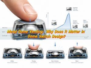
During actuation, the dome displaces air from the cavity as its crown moves toward the center pad. During release, air must return while the dome recovers. The same lateral path normally serves both directions. If that route is restricted, the user can feel pneumatic damping in addition to the mechanical force curve of the dome.
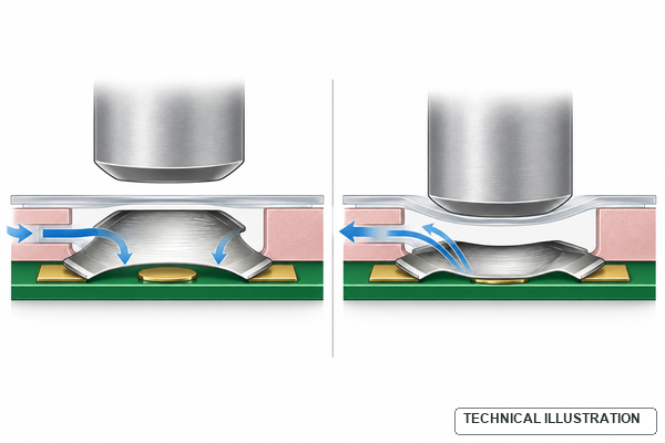
The vent should therefore be evaluated with the actuator and circuit support installed. A centered actuator can produce a clean collapse, while an off-center or oversized actuator can distort the dome and make an airflow problem appear to be a dome-force problem. Venting and force transfer should be reviewed together, but they perform different functions.
What Makes a Complete Air Path?
A complete path has a defined start and endpoint on every manufactured layer. On a custom dome array, we review the PET outline, spacer cut, adhesive land, circuit pads, registration features and enclosure boundary as one route. The air path cannot be approved from a top-layer outline alone.
Common endpoints include a controlled opening at an unsealed edge, a vent through the PCB, a top vent through an approved polyester region, a shared manifold, or a closed internal reservoir with enough volume for repeated key action. The correct endpoint depends on the product seal, PCB construction, contamination risk, key spacing and housing volume.
A through-board vent must avoid traces, components and sensitive cavities on the opposite side. A top vent must not sit beneath a key feature that seals it during use. An internal reservoir must not collapse when screws, ribs or gaskets load the enclosure. Each option needs an assembly-level check.
Which Vent Topology Fits the Key Layout?
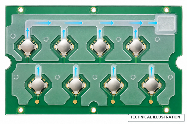
Choose the topology from the number of keys, available adhesive land and permitted endpoint. A short dedicated route is easy to isolate, while a shared route saves space and can simplify dense arrays. Shared routing adds a new requirement: branches must remain balanced enough that one key does not strongly affect another.
| Topology | Best fit | Main design check |
|---|---|---|
| Dedicated channel | Single keys or widely spaced domes | Every route reaches a permitted endpoint and retains adequate adhesive land |
| Shared trunk with branches | Multi-key arrays with limited routing space | Branch resistance and path length do not create key-to-key feel differences |
| Segmented manifolds | Large keypads with functional zones | A blockage or rapid key sequence in one zone does not influence the entire array |
| PCB vent | Assemblies with a verified open volume below the board | Opposite-side components, coating and housing do not close the route |
| Protected internal reservoir | Sealed or splash-resistant enclosures | Reservoir volume and serpentine path remain open under enclosure compression |
A single-layer metal dome array can use carrier openings or coordinated board-level venting when the stack permits. A double-layer metal dome array uses a spacer beneath the top film, giving the designer a defined plane for cavities and channels.
How Should the Spacer and Adhesive Form the Channel?
The spacer cut usually defines the cavity and the narrow route that leaves it. The drawing should show the channel as a manufactured feature, not as an informal note. Its entry must stay outside the contact pattern, while the remaining adhesive land must retain and seal the dome array without lifting at corners.
Channel width alone does not determine performance. Usable flow also depends on spacer thickness, adhesive rheology, die-cut accuracy, liner removal and lamination pressure. A narrow design can close when adhesive creeps inward; an oversized cut can reduce bond area or allow the PET to flex over an unsupported gap. We therefore review the nominal geometry together with material and process tolerances.
Sharp dead ends and thin adhesive bridges deserve special attention. Rounded transitions are easier to manufacture consistently than decorative, highly intricate paths. The route should be as simple as the product boundary allows, with inspection access at the cavity and endpoint.
How Does Dome Geometry Change the Vent Entry?
Dome geometry changes where air can leave the cavity and how much adhesive support is available. A four-leg metal dome has open sectors between its legs, so the spacer entry can align with a clear sector while preserving support near the legs. The channel should not force the dome edge to sit over an unsupported cut.
A circle metal dome has a continuous perimeter. Its vent route usually depends more on spacer clearance, a carrier opening or a coordinated PCB vent. The design team should not copy a four-leg vent entry onto a round dome without checking edge support and cavity clearance.
Triangle and oblong domes add directional stiffness and tighter local clearances. For any shape, keep the vent decision separate from holes or dimples formed in the metal dome. Changing the stamped dome body can alter the force curve, fatigue behavior or contact geometry and needs its own mechanical validation.
How Do You Balance Shared Channels Across a Dome Array?
A shared manifold should not make the first key easy to vent and the last key noticeably restricted. Keep branch geometry consistent where practical, avoid unnecessary length differences and divide very large layouts into zones. The aim is not mathematical symmetry; it is similar pneumatic behavior at the assembled keys.
Rapid multi-key operation is a useful stress case. If one press displaces air toward a neighboring cavity, the adjacent key can feel different or its overlay can move slightly. Segmented branches, adequate trunk volume and a protected endpoint reduce this coupling. The effect must be checked in the real enclosure because open-bench tests provide more free volume than the product may have.
Keys with different dome sizes or forces may require different branch treatment. Do not assume one manifold geometry serves every key simply because the domes share one PET carrier.
How Can a Sealed Keypad Vent Without Creating a Water Path?
A sealed keypad does not require every dome cavity to connect directly to the exterior. The air path can remain inside the sealed boundary and terminate in a protected reservoir. A longer or serpentine route can separate the dome cavities from an exposed edge, provided the added restriction still allows the required press and release response.
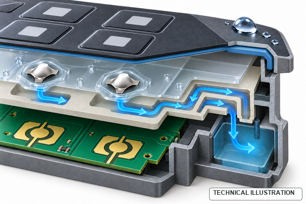
Keep the perimeter gasket continuous and avoid a straight capillary path from the enclosure edge to the dome cavity. The reservoir must remain inside the protected volume and must not be crushed by ribs, fasteners or local foam. Splash resistance, immersion requirements and cleaning chemistry are product-level requirements; the vent layout supports them but does not establish an IP rating by itself.
Which Assembly Features Can Block the Designed Vent?
A correct die-cut drawing can still fail after assembly if another part closes the route. Review all interfaces that cross or compress the vent plane. The final stack should be checked at nominal and tolerance-limit conditions.
- Overlay embossing or a rigid key feature can press the PET into the channel.
- Housing ribs, screws or clips can compress the spacer above a trunk or reservoir.
- Adhesive squeeze can narrow a branch after lamination.
- Conformal coating or gasket material can close a PCB vent on the opposite side.
- A misregistered dome sheet can shift the channel entry under a dome leg.
- Dust seals, foam or potting added late in the project can isolate the endpoint.
The most reliable review overlays the mechanical enclosure, dome-array die line and PCB data using common datums. That check is more useful than reviewing separate screenshots from each supplier.
What Should the Drawing Specify?
The release package should define the air path with the same discipline used for dome coordinates and board contacts. Avoid notes such as “add vent as needed” because they do not identify the responsible layer or endpoint.
| Drawing item | What to define | Why it matters |
|---|---|---|
| Stack-up | Overlay, PET, spacer, adhesive, circuit and support layers | Identifies the physical plane that carries the path |
| Dome cavity | Outline, clearance and dome center datum | Protects collapse, return and registration |
| Channel entry | Location relative to dome legs and contact pads | Prevents electrical interference and unsupported edges |
| Route and endpoint | Dedicated/shared topology, trunk, PCB hole or reservoir | Confirms that the path is continuous after assembly |
| Keepouts | Minimum adhesive land, traces, ribs, gaskets and coating zones | Prevents blockage and bond loss |
| Materials and tolerances | PET, adhesive, spacer thickness, die-cut and registration limits | Allows a manufacturability review instead of nominal-only approval |
Include the enclosure cross-section when sealing or internal routing matters. Gerber, DXF, CAD, PDF and stack-up information can be reviewed together; a single 2D outline rarely shows every compression boundary.
Which Prototype Tests Confirm the Air Path?
Prototype testing should compare the approved tactile target with the complete assembly. A force curve from a loose dome is useful for component control, but it cannot confirm whether the product’s air path remains open.
| Test | What it reveals | Recommended comparison |
|---|---|---|
| Slow press and release | Damping, delayed recovery or uneven collapse | Loose dome, open stack and final enclosure |
| Rapid repeated actuation | Recovery limits and shared-channel interaction | Single key versus adjacent-key sequences |
| Force-curve measurement | Peak force, return force and assembled variation | Center keys, edge keys and longest vent branches |
| Temporary blockage check | Whether the tested path actually controls tactile behavior | Normal path versus intentionally blocked endpoint |
| Temperature and dwell | Adhesive flow and material effects over time | Initial sample versus conditioned assembly |
| Splash or seal validation | Whether the route creates an environmental entry path | Product-specific method and enclosure requirement |
Record the tested stack-up, actuator and enclosure condition with the result. Otherwise a successful open-fixture test can be mistaken for approval of the production assembly.
What Failure Pattern Points to a Venting Problem?
Venting problems often resemble dome-force, adhesive or actuator problems. Diagnose them by changing one boundary at a time and comparing keys with different path lengths.
| Observed pattern | Likely air-path question | Next check |
|---|---|---|
| Key feels heavier only after final enclosure assembly | Housing feature or gasket may compress the path | Inspect the stack under actual screw load |
| Release is slow but press still closes the circuit | Return airflow may be restricted | Compare endpoint open versus temporarily blocked |
| Keys at one end of an array feel different | Shared branch length or trunk restriction may be uneven | Map force curves against vent position |
| Adhesive lifts near the route | Channel may remove too much bonding land | Review cut geometry, surface preparation and lamination |
| Seal test fails near a vent edge | Endpoint may bypass the protected boundary | Reroute to an internal reservoir or protected location |
| Random production variation | Die-cut registration or adhesive flow may narrow the entry | Inspect actual parts, not only nominal CAD |
A vent-related hypothesis should be verified, not assumed. Contamination, pad finish, actuator misalignment, dome damage and PCB flex can create similar symptoms.
What Should You Send for Our Venting Review?
EBest Circuit(Best Technology) manufactures metal domes and custom metal dome arrays and can review the vent path together with dome selection, PET carrier, adhesive spacer, PCB or FPC contacts and the actuator interface. Our published array options include single-layer and double-layer constructions, and we support custom positions, shapes and mixed dome specifications on one carrier when the design is suitable.
For an engineering review or quotation, send the keypad layout, PCB/FPC data, dome coordinates and preferred series, force and travel targets, complete stack-up, actuator section, enclosure compression features, sealing requirement, operating environment, validation plan and forecast quantity. Mark the intended vent endpoint or protected volume if it is already defined.
A manufacturable metal dome venting design must remain continuous after every layer is laminated and the enclosure is tightened. Send your drawing package to sales@metal-domes.com; we will review the air path as part of the complete tactile switch stack rather than as an isolated slot.