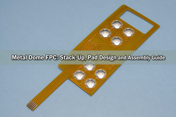
Metal dome FPC combines a flexible printed circuit with snap-action metal contacts to create a thin, tactile switch assembly that can route through narrow or curved enclosures. The FPC carries the contact pads and traces, while the dome supplies the momentary electrical closure and tactile click. Reliable operation depends on the whole stack: pad geometry, coverlay opening, venting, dome retention, local support, bend location and connector design.
What Is a Metal Dome FPC?
A metal dome FPC is a normally open momentary switch built on a flexible copper circuit. A formed stainless-steel dome sits over an isolated center contact and an outer contact. Pressing the dome makes its center touch the inner pad while its perimeter or legs remain connected to the outer pad, closing the circuit. Releasing the load lets the dome recover and reopen the contact.
The construction is useful when a rigid PCB would occupy too much space, require a separate wire harness or prevent the switch panel from following the enclosure. The flexible tail can carry several keys to a ZIF connector, soldered connector or rigid control board. The active key area, however, should behave like a stable switch platform rather than a freely flexing cable.
How Does a Metal Dome FPC Work?
The switch closes through a snap-through event. Load rises as the dome deflects, reaches the trip force and then drops as the formed shell inverts toward the center pad. This force drop produces the tactile response. Electrical closure should occur within the controlled travel window, and the dome should return completely when the load is removed.
The dome is only one part of the force path. A keycap, plunger or overlay transfers the user’s load; the carrier film holds the dome in position; the FPC pads complete the circuit; and the backing structure resists deflection. A soft unsupported circuit can absorb travel before the dome snaps, while excessive preload can reduce travel or prevent full recovery.
Which Stack-Up Is Used for a Metal Dome FPC?
A practical stack usually places a PET dome-array carrier and pressure-sensitive adhesive above the metal dome, with the dome seated on exposed FPC contacts and a stiffener or housing support below the active area. The exact layer count changes with sealing, illumination and actuator requirements, but each layer needs a defined mechanical function.
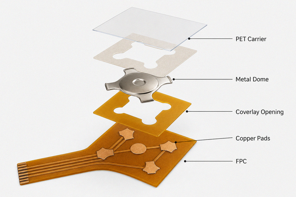
| Layer or feature | Primary function | Design control |
|---|---|---|
| Overlay or actuator | Transfers finger or plunger load | Centering, contact-face diameter and maximum stroke |
| PET carrier and adhesive | Retains and locates the dome | Pocket alignment, adhesive clearance and air path |
| Metal dome | Provides snap action and electrical bridging | Shape, force, travel, height and life requirement |
| Coverlay opening | Exposes the contact area | Clearance from dome legs and registration tolerance |
| Copper contact pattern | Forms the open switch circuit | Center isolation, outer support and finish flatness |
| FPC and stiffener | Routes signals and supports the key area | Local rigidity, neutral bend region and connector thickness |
A custom metal dome array can integrate the dome-retention film with the key pattern, tail orientation and mixed dome positions required by the FPC layout. The released stack drawing should identify material, thickness, adhesive zones and the reference side used for alignment.
How Should FPC Contact Pads Be Designed?
The center contact must be electrically isolated from the outer contact, while the outer geometry must support every dome leg or rim on one plane. Copper balance, plating thickness, coverlay registration and local flatness all affect seating. Traces should leave the pad without creating raised steps beneath a dome foot, and vias should stay outside the mechanical support area unless the structure has been specifically validated.
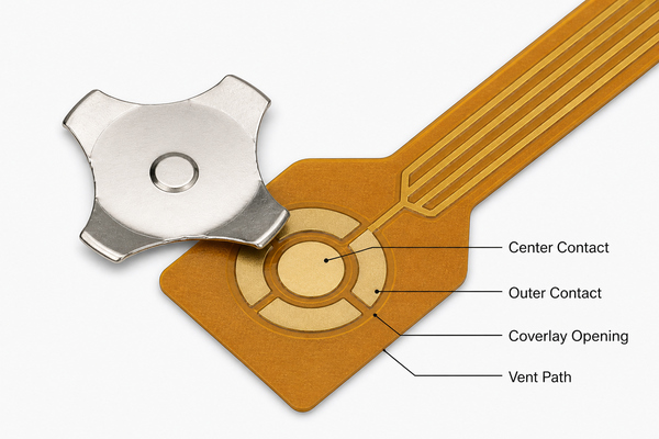
The contact finish should remain flat, clean and corrosion resistant for the intended environment. A finish that is acceptable for a connector is not automatically suitable beneath a repeatedly moving dome if its thickness distribution produces an uneven seat. The pad drawing should define the center diameter, outer support geometry, minimum isolation gap, dome orientation and vent connection rather than using a generic switch symbol.
The same support principles used in PCB contact pad design for metal dome switches apply, but FPC adds coverlay registration, dynamic bending and local stiffness variables that do not exist on a thick rigid board.
Why Are Coverlay Openings and Vent Paths Critical?
The coverlay opening must expose the complete functional contact area without interfering with dome travel. If the opening edge sits beneath a dome leg, the resulting height step can tilt the dome, shift trip force and create unstable contact. If the opening is excessively large, it removes useful insulation and reduces the margin available for adhesive or environmental sealing.
Every dome cavity also needs a controlled route for air to leave and re-enter during actuation. A sealed cavity can raise force, slow return or make keys feel different as ambient pressure changes. The vent may use open sectors between four-leg dome arms, a die-cut channel in the spacer or a connected manifold, but it must not terminate under adhesive or inside a liquid trap. The metal dome venting guide explains how the air path interacts with sealing and switch response.
Which Metal Dome Shapes Work Best on FPC?
Shape selection starts with available footprint, force range, actuator geometry, contact pattern and venting strategy. Four-leg domes are common on flexible circuits because their defined feet create stable support points and leave open sectors for routing or ventilation. Circle domes provide symmetric perimeter support, while triangle and oblong shapes solve compact or narrow key layouts.
| Dome shape | Useful FPC characteristic | Main layout check |
|---|---|---|
| Four-leg | Defined feet and open sectors around the contact | Foot coplanarity, orientation and vent alignment |
| Circle | Symmetric response in a round key envelope | Continuous outer support and cavity venting |
| Triangle | Compact three-point support | Orientation and actuator centering |
| Oblong | Fits narrow controls or elongated keycaps | Load position along the long axis |
A four-leg metal dome is a practical starting point when the FPC pad can support all four feet and the actuator can remain centered. Final selection should follow the released part drawing; shape names alone do not define trip force, travel, height or life.
When Does an FPC Need a Stiffener Under the Dome?
An FPC needs local reinforcement when the enclosure cannot provide a flat, rigid reaction surface beneath the active key area. Without support, the circuit bends as the user presses, consuming stroke and changing the force curve. A stiffener can also stabilize the contact plane, protect traces near the keys and maintain consistent stack height.
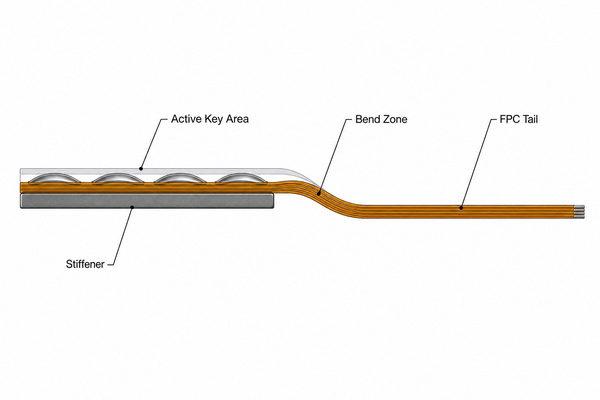
The reinforcement should end before the dynamic bend begins. A sharp stiffness transition directly beneath a dome, trace neck-down or connector termination concentrates strain. Polyimide stiffeners suit controlled thickness and compact assemblies; FR4 or metal backing can provide greater rigidity where space allows. The selected material, adhesive and thickness should be included in the mechanical tolerance stack.
How Should a Dome Array Be Laminated to FPC?
Lamination should place every dome concentrically over its matching contact pattern without adhesive entering the support or contact area. Registration targets outside the functional footprint help align the carrier to the FPC. The process should control cleanliness, lamination pressure, carrier tension and trapped air so the film does not preload or distort individual domes.
- Clean and inspect the FPC contact surface before lamination.
- Use tooling holes, fiducials or optical targets that reference the copper pattern.
- Keep adhesive cutouts clear of dome legs, vent paths and exposed contacts.
- Apply pressure through a fixture that supports the circuit without depressing the domes.
- Inspect dome position, film wrinkles, trapped particles and vent continuity after lamination.
A single-layer dome array provides a compact retention structure for straightforward layouts, while a double-layer dome array can provide additional spacing or air-channel control where the construction requires it. The layer choice should match the sealing, venting and stack-height design rather than being treated as a cosmetic option.
How Do Bend Zones, Tails and Connectors Affect the Layout?
The FPC should bend in a dedicated region away from dome footprints, stiffener edges, coverlay corners and solder joints. Conductors should cross the bend smoothly, with unnecessary width changes and acute corners removed. Repeated-flex applications require a different copper, stack and routing strategy from a one-time installation fold.
The tail termination sets its own constraints. A ZIF tail needs controlled finished thickness, exposed-finger length, stiffener position and contact-side orientation. A soldered connector adds assembly heat and a rigid mass, so strain relief becomes important. If the FPC connects directly to another board, the tail route should be checked in the actual enclosure for insertion access, minimum bend radius and tolerance at both endpoints.
Which Tests Verify a Metal Dome FPC Assembly?
Verification should combine mechanical, electrical and assembly checks because a tactile click does not prove stable electrical contact. Measure the finished assembly with its intended backing and actuator whenever those parts can change preload or support.
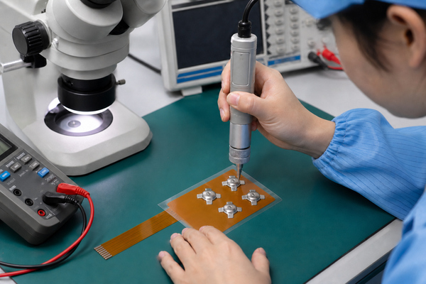
- Force-displacement testing records trip force, return force and travel.
- Continuity or contact-resistance testing confirms make and break at defined positions.
- Optical inspection checks dome centering, coverlay registration, film condition and contamination.
- Life cycling tracks changes in force, travel, resistance and return behavior.
- Temperature, humidity and storage tests evaluate adhesive movement, oxidation and dimensional change.
- Dynamic-flex testing applies when the tail must move repeatedly in service.
Test fixtures must support the same key area and preserve the same vent condition for every sample. A rigid laboratory plate can hide a weak enclosure support, while a sealed test fixture can falsely raise force. Record fixture revision, probe geometry, speed, travel stop and electrical threshold with the results.
What Common Metal Dome FPC Failures Should Be Prevented?
Most field problems can be traced to a mismatch between the mechanical stack and the flexible circuit rather than to the dome material alone. The observed symptom helps identify which interface to inspect first.
| Symptom | Likely mechanism | Corrective direction |
|---|---|---|
| High or inconsistent force | Blocked vent, coverlay step, off-center dome or flexible backing | Restore the air path, correct registration and support the active area |
| Intermittent closure | Contamination, uneven pads, shifted dome or insufficient travel | Control cleanliness, flatness, alignment and actuator stroke |
| Slow or incomplete return | Excess preload, adhesive intrusion or carrier-film creep | Reset stack height and clear the dome envelope |
| Trace cracking near keys | Bend or stiffener edge located in the active region | Move the flex transition and smooth the conductor geometry |
| Key-to-key feel variation | Unequal support, lamination shift or cavity pressure differences | Use common datum control and consistent backing and vents |
Preventing over-travel is especially important. The enclosure or guided actuator should provide the hard stop so the dome is not forced beyond its validated stroke. The dome array adhesive selection also needs to account for temperature, humidity, bond surface and long-term creep.
Where Is a Metal Dome FPC Used?
Metal dome FPC assemblies fit products that need tactile keys, a thin profile and flexible routing between the user interface and control electronics. Typical uses include handheld instruments, medical controls, automotive interior buttons, appliance panels, access devices, industrial keypads and compact consumer electronics.
They are less suitable where a switch must carry high current, provide maintained latching action or operate directly under severe contamination without an engineered seal. They are also unnecessary when a rigid PCB already fits the enclosure and a separate FPC adds no routing or assembly benefit. The architecture should be selected from enclosure geometry, key count, movement, sealing and service requirements.
FAQ About Metal Dome FPC
Can a metal dome be placed directly on an FPC?
Yes, provided the FPC has a compatible center-and-outer contact pattern, a clear coverlay opening, a controlled vent and adequate backing. A loose dome also needs reliable retention through a carrier film, spacer or mechanical structure.
Is a stiffener always required under an FPC dome switch?
No. A stiffener is unnecessary when the enclosure supplies a flat, rigid and dimensionally controlled support beneath the entire active area. It becomes useful when the circuit would otherwise flex, wrinkle or sit across gaps.
Can the FPC bend directly below a metal dome?
It should not. Bending below the contact changes support during actuation and increases strain around pads and traces. Keep the dynamic bend outside the dome footprint and beyond the stiffener transition.
How is a metal dome retained on the FPC?
A die-cut PET carrier with pressure-sensitive adhesive is a common method. The carrier locates the dome while cutouts and channels preserve motion and venting. Mechanical pockets or integrated overlays are alternatives when the enclosure controls retention.
What determines the feel of an FPC dome switch?
Dome force and geometry are only the starting point. Actuator size, preload, backing stiffness, carrier film, overlay, trapped air and maximum stroke all change the finished key response.
Conclusion
A reliable metal dome FPC treats the flexible circuit, contact pads, dome array, vent path, stiffener, bend zone and actuator as one mechanical-electrical system. EBest Circuit(Best Technology) has manufactured metal domes and dome arrays since 2006 and supports custom arrays assembled with PCB or FPC from CAD, PDF, Gerber and customer drawings, including prototypes, low-volume builds and scalable production. For a project-specific stack and dome-array review, use the Metal Dome and Dome Array contact page.