A 9mm T series snaps dome is a triangular stainless-steel snap contact selected by its 9 mm size, trip force, leg configuration, surface finish, PCB contact pattern and actuator geometry. The phrase is used inconsistently in search results, so the first engineering step is to confirm that the requirement is for a 9 mm T-series metal dome rather than an ammunition snap cap or a clothing fastener.
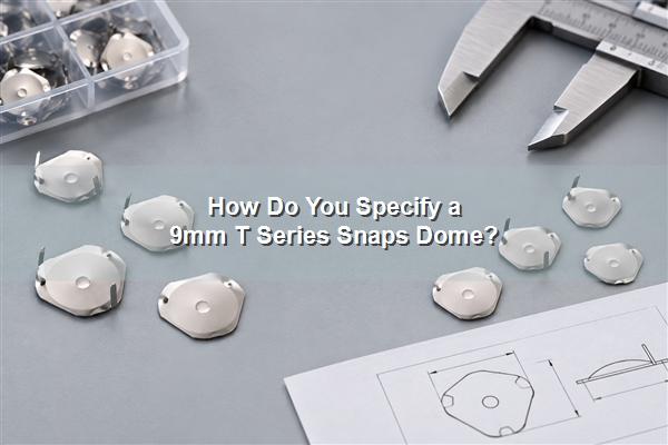
This guide explains the available 9 mm force options, the difference between legged and legless parts, the reference PCB pad geometry, actuator alignment, finish selection and assembly controls. The goal is to convert a short product name into a buildable metal dome PCB switch specification.

What Is a 9mm T-Series Snap Dome?
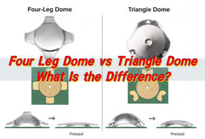
A 9 mm T-series snap dome is a triangle metal dome that works as a normally open, momentary switch contact. Its outer contact points rest on the PCB or flex circuit, while the center of the dome snaps downward under load to bridge the center contact. Releasing the actuator lets the dome recover and open the circuit.
The 9 mm designation refers to the nominal dome size, not the complete keypad button diameter. Overlay embossing, plunger diameter, PCB clearance and the retaining carrier all need additional space. Our broader T-series range covers 5–13 mm with typical trip forces from 150 to 6,000 gf, but the available combinations for one 9 mm design must be confirmed from its specific drawing.
Which 9mm T-Series Forces and Part Options Are Available?
Our current 9 mm drawings separate the options by mounting structure. The table keeps those published part families together so the choice can begin with both force and assembly method.
| 9 mm option | Published trip-force choices | Typical selection reason |
|---|---|---|
| M9T with 1.5 mm legs | 140, 200, 300, 400, 500, 600 and 800 gf | Mechanical location through matching PCB holes |
| M9T-D without legs | 140, 200, 300, 400, 500, 600, 800 and 1,800 gf | Carrier film, pocket or another controlled retention method |
Trip force is not the only tactile target. The drawing review should also address return force, click ratio, travel, dome height and tolerance. A heavier tactile metal dome may reduce accidental activation, but it also increases actuator load and can feel harsh if the overlay or plunger adds stiffness.
Should You Choose a Dome With Legs or Without Legs?
A legged 9 mm dome locates mechanically in PCB holes. This is useful when the dome must resist rotation before the overlay or carrier is applied, or when temperature makes pressure-sensitive adhesive less attractive. The leg length must match the PCB thickness and hole construction; excessive projection can interfere with the opposite side of the assembly.
A legless dome uses a carrier, formed pocket or other controlled retention. It avoids through-holes and can support a thinner, cleaner routing area. The trade-off is that placement accuracy now depends on the retaining layer and lamination process. Common T-series leg lengths include 0.8, 1.5 and 3.0 mm, with 2.0 mm used less often, but the selected part drawing remains authoritative.
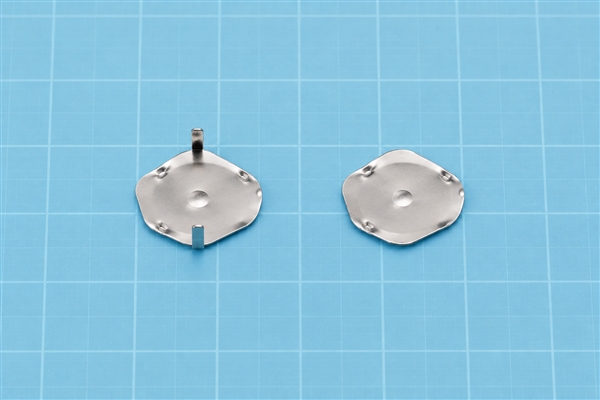
We do not recommend soldering the legs. Solder heat and rigid restraint can change the spring behavior, reduce click quality or shorten service life. The legs are intended primarily for location and retention in the matching holes.
How Does the 9mm Triangle Dome Make Electrical Contact?
The metal dome structure combines a raised spring crown with outer support points and a central switching area. At rest, the center remains above the PCB center pad. A centered load drives the crown through its snap point, the center closes the circuit, and stored spring energy returns the dome after release.
That behavior is why a snap dome switch gives a clearer tactile event than a flat conductive contact. The electrical result still depends on clean pads, suitable finish, controlled actuator travel and sufficient separation between the center pad and outer contact. The dome shape alone cannot compensate for a contaminated surface or a shorted PCB pattern.
What PCB Pad Layout Fits a 9mm T-Series Dome?
Our single-sided PCB reference drawing for the 9 mm triangle series lists D = 10.27 mm, I = 7.48 mm, P = 3.81 mm, F = 0.89 mm and S = 1.00 mm. These callouts define the reference contact and leg-hole geometry shown on that drawing. They are a starting point, not a universal footprint.
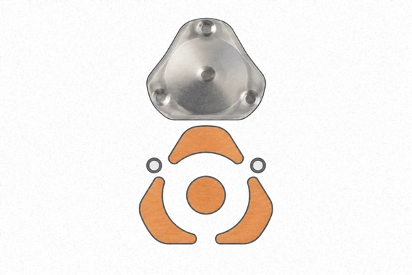
For a reliable metal dome PCB switch, keep the center switching pad electrically isolated from the outer contact, verify the leg-hole position against the exact M9T drawing, avoid solder-mask ridges under the support points and provide a clean, level seating surface. Trace exits should not create a step that rocks the dome. The final pad layout belongs in the customer’s controlled PCB drawing and should be checked against the selected dome sample before production release.
How Should the Actuator Press the Dome?
The actuator should load the crown close to its center. A small off-center plunger can tilt the triangle dome, raise apparent force and wear one support point. An oversized actuator may press the outer legs or carrier before the crown reaches its snap point. The actuator diameter, tip radius, clearance and alignment tolerance therefore belong in the same review as the dome force.
Mechanical stop height is equally important. The actuator needs enough travel to cross the snap point and close the contact without crushing the dome after closure. Metal dome buttons that use a molded rubber key, plastic plunger or embossed overlay can each produce a different finished force curve even when the loose dome is identical.
Which Surface Finish Should You Select?
Stainless steel, nickel-plated, silver-plated and gold-plated options serve different contact environments. Finish selection should consider PCB surface finish, target contact resistance, humidity, contamination, current level, storage time and lifecycle. A more conductive finish does not correct poor pad geometry or insufficient contact wipe.
The series-level electrical data lists SPST normally open behavior, contact bounce below 0.3 ms on closure and below 6 ms on release, a maximum switching condition of 12 mA at 24 V DC and breakdown voltage above 200 V. These are component-level reference conditions; the finished circuit must be verified at its real load, debounce strategy and environment.
How Do You Prevent Rotation, Misalignment and Trapped Air?
Legged triangle domes use their holes to resist rotation, but hole position and PCB flatness still control the seating result. Legless domes need a precisely registered pocket or carrier. In both cases, the actuator centerline should remain over the crown through the full tolerance stack.
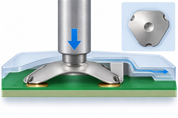
A sealed overlay also changes cavity pressure. If air cannot move through a controlled internal path, trapped pressure may increase force, slow rebound or couple adjacent keys. The vent should remain inside the protected assembly and must not become an ingress path to the board edge. Inspection should check dome orientation, flat seating, carrier registration and free return before electrical testing.
When Should a 9mm T-Series Dome Be Supplied in a Dome Array?
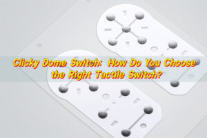
Loose domes suit manual installation, prototype evaluation or a process that already has a reliable placement method. A metal dome array holds the parts in a registered carrier. A single-key dome array can protect one 9 mm dome during handling and simplify placement on a metal dome membrane switch or PCB assembly.
Carrier design must preserve the snap action and any required vent path. Adhesive should not creep under a contact point, and the pocket should not preload the crown. For higher-volume equipment, metal dome packing options such as tube or tape-and-reel can be considered against the placement equipment, orientation control and lot size.
Where Are 9mm Triangle Metal Domes Used?
A 9 mm triangle dome is useful when the design needs strong tactile feedback in a compact angular footprint. Handheld controls and game interfaces use the clear snap to confirm input. Industrial panels may select a higher force to reduce accidental operation. Medical or test equipment can use the stable multi-point contact when the actuator and enclosure maintain alignment.
Desktop phones, appliance panels and specialized remote controls can also use the shape when the PCB routing or key geometry favors a triangle footprint. The application name does not select the dome by itself: operating force, expected cycles, contamination, temperature, user population and actuator stack determine whether the 9 mm option is appropriate.
What Should You Send for Engineering Review?
As a metal dome manufacturer, we need the complete switching stack rather than only a nominal diameter. Send the target force, preferred leg condition, PCB thickness, pad and hole drawing, actuator geometry, available over-travel, circuit load, surface finish, environment, lifecycle target, packaging method and annual quantity.
- Identify whether the 9 mm dome must use 1.5 mm legs or a legless carrier.
- State trip force together with acceptable tolerance, return force or click-ratio expectations.
- Provide Gerber, PCB/CAM, AutoCAD, PDF or another controlled drawing for alignment review.
- Define whether the supply is loose domes, a retained array or an automated-placement package.
- List electrical, environmental and life-test acceptance conditions.
EBest Circuit(Best Technology) has manufactured metal domes since 2006. We can review trip force, rebound force, dimensions, electrical behavior and life requirements, and we can evaluate a custom metal dome when a catalog option does not match the stack. Start with our T-series metal dome range, then send the controlled inputs to our engineering team at sales@metal-domes.com. A correctly specified 9mm T series snaps dome should be released only after the selected part, PCB footprint and finished actuator stack have been verified together.