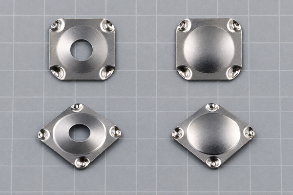
A square metal dome is a square-bodied tactile contact with a circular snap area in the center and four small ball-shaped feet formed at the corners. It is available with or without a center hole. Choose this geometry when the switch stack benefits from a square envelope, four-corner support or a custom trip-force target, but always design the PCB contact pattern and actuator around the approved dome drawing.

What Is a Square Metal Dome?
The square tactile dome shown in our product range has a nearly complete rounded-square body, a circular domed center and four ball-shaped corner feet. It is not the same component as a cross-shaped F-series dome. Pressing the center makes the curved section snap downward and close the switch against the circuit contact; releasing the load allows it to recover.
The terms square tactile dome and square snap dome may describe the same basic part family. The drawing remains the controlling document because overall size, height, center-hole option, trip force and contact geometry can vary by part.
How Do the Four Corner Feet Support the Snap Action?
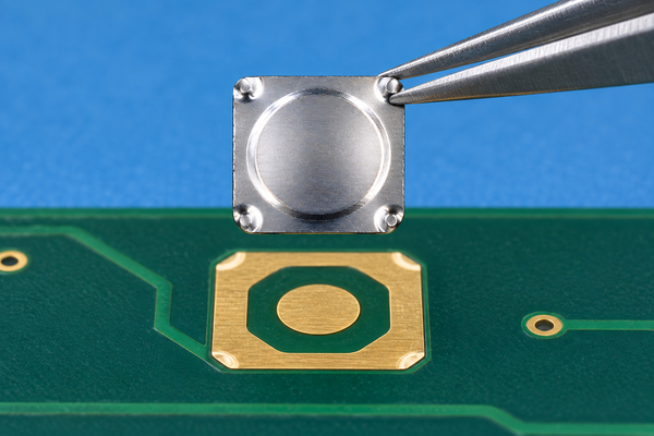
The four corner feet establish the support points around the central snap area. When the actuator loads the center, the dome deflects between those supports until it reaches the trip point. The feet must sit evenly on the intended outer contact region; a raised mask edge, debris or uneven copper beneath one corner can tilt the dome and change the force response.
The square body also gives assembly equipment and inspection systems a visible orientation reference. That does not mean every design needs a directional footprint. The required orientation follows the approved drawing, PCB contact geometry and carrier layout rather than a generic assumption about square domes.
Should You Specify a Center Hole or a No-Hole Dome?
Both center-hole and no-hole versions are shown in our square-dome range. A center hole may be considered when the switch stack needs a defined opening for air movement, light transmission or mechanical clearance. A no-hole version provides an uninterrupted central surface for the actuator. These are design options, not interchangeable cosmetic features.
Confirm the hole diameter, actuator tip and any lighting or vent path together. The actuator must still load the intended central snap area without catching the hole edge or contacting a corner foot.
When Is a Square Dome Better Than a Round Dome?
A square dome is worth evaluating when the available key area is square, the design benefits from four defined corner supports, or the required trip force is difficult to obtain with a conventional dome geometry. Our product information notes that custom square domes can be made with higher trip forces than traditional dome designs, subject to the selected size, material and engineering review.
A round dome may be simpler when rotational orientation must be irrelevant or the existing PCB uses a circular outer contact. Neither shape is universally better. Compare the available envelope, actuator guidance, force and travel targets, contact layout, sealing method and production placement process before selecting the geometry.
How Should the PCB Contact Pattern Be Designed?
The PCB normally needs an electrically isolated center contact and an outer contact region that supports the dome at the specified locations. Do not copy a four-pad pattern merely because the part has four corner feet. The approved part drawing and electrical design must determine whether the outer contact is continuous or segmented and where each corner is supported.
- Match the footprint to the exact dome outline, corner-foot positions and center-contact area.
- Keep solder, vias, raised solder mask and component bodies outside the active footprint.
- Check flatness and surface cleanliness across all four support locations.
- Apply manufacturing tolerances to the PCB, carrier and placement datums before approval.
How Should the Actuator Load the Dome?
The actuator should apply a centered, primarily vertical load to the circular snap area. Its contact face and travel must be compatible with the selected dome and any center hole. An off-center plunger can make one corner carry more load, while an oversized face can interfere with the square body or carrier.
Evaluate the production-intent stack, including the keycap, rubber key or plunger, overlay, spacer, adhesive and housing guide. A loose-dome finger test cannot represent the final tactile response when those layers add preload, side load or travel limits.
How Do Venting, Adhesive and Sealing Work Together?
The cavity needs a controlled way to move air as the dome snaps and returns. The vent may be created through the PCB, spacer or adhesive network, depending on the circuit construction. It must not be blocked by adhesive squeeze-out or placed where it creates an uncontrolled path for dust, moisture or cleaning residue.
For a sealed keypad, review the vent route together with the overlay and adhesive perimeter. The goal is predictable tactile recovery without sacrificing the environmental protection required by the finished assembly.
Should the Domes Be Supplied Loose or in an Array?
Loose domes can suit samples, manual prototypes or equipment designed to place individual parts. For a multi-key layout, a registered custom dome array can control dome position and orientation in one carrier. The carrier design must match the final circuit datum, vent path and adhesive opening.
A single-key dome array is another peel-and-place option when separate switch locations must be installed individually. Select the packaging format from key count, placement equipment, production volume, rework needs and cleanliness requirements.
Which Specifications Belong on the Drawing?
Do not reuse the size, force or life values of a different metal-dome series. A square-dome request should define the required values for the actual part and application.
| Drawing input | Why it matters | Review point |
|---|---|---|
| Overall length and width | Sets the switch envelope | PCB area, carrier opening and nearby clearance |
| Dome height and travel | Controls stack movement | Actuator stroke and housing stop |
| Trip and return force | Defines operating feel | Tolerance after the complete key stack is assembled |
| Center-hole option | Changes the central interface | Hole diameter, light or vent path and actuator tip |
| Corner-foot geometry | Defines support locations | Outer contact region, flatness and placement datum |
| Material and finish | Affects contact and environment | Circuit finish, corrosion exposure and validation plan |
Which Assembly Defects Should Be Checked?
Incoming and in-process inspection should identify missing, doubled, inverted, rotated or offset domes; damaged corner feet; scratches or dents in the snap area; contamination; blocked vents; adhesive intrusion and carrier wrinkles. A visually square outline helps reveal rotation, but appearance alone cannot confirm electrical closure or tactile performance.
Use the PCB datum and approved coordinates for placement checks. If the domes are supplied in an array, verify both carrier-to-circuit registration and each dome’s position within the carrier.
How Should Tactile and Electrical Performance Be Validated?
A centered force probe can measure trip force, return force and travel while the electrical circuit records the closure point. Validation should use the intended PCB finish, adhesive construction and actuator because the assembled stack can behave differently from a loose component.
Life testing, environmental conditioning and post-test inspection should follow the actual product requirement. Do not apply a cycle-life value from an unrelated dome family to the square part. Acceptance limits should be agreed for the selected drawing and operating conditions.

What Should You Send for a Square-Dome Quotation?
Send the PCB or FPC contact drawing, available envelope, trip-force target and tolerance, travel target, center-hole requirement, actuator details, overlay and adhesive stack, sealing requirement, expected life, packaging preference and order volume. Photos of the existing switch help explain the stack but do not replace dimensioned files.
EBest Circuit(Best Technology) can review these inputs against a standard or custom metal dome solution. We will check the square body, corner-foot support, actuator interface, contact layout and packaging method before confirming feasibility. Send your files to sales@metal-domes.com.
For the fastest review, identify the exact square metal dome requirement in the drawing instead of referencing a different four-leg series. That keeps the quotation, prototype and production checks tied to the same component geometry.