

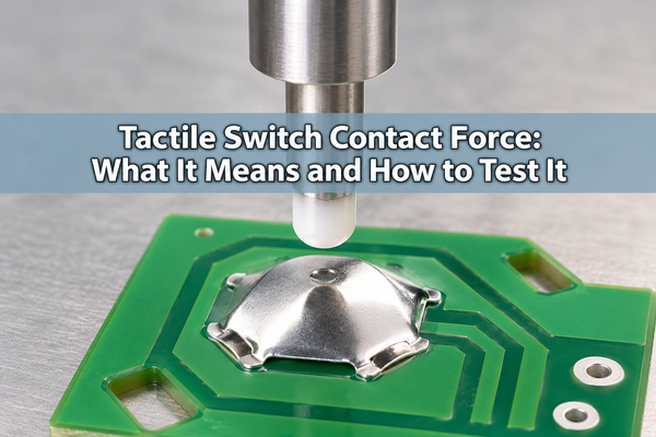
Tactile switch contact force is an ambiguous specification unless the measurement point is defined. In a metal-dome key, the force your finger applies, the peak force before snap-through, and the pressure at the electrical contact are related but not interchangeable. To approve a design, measure force and electrical closure on the same assembled key, with the actuator, PCB and test conditions documented.
What Does Tactile Switch Contact Force Mean?
In product listings, the phrase may refer to the external force needed to make the switch close. In contact mechanics, it can instead mean the normal force pressing the two conductive surfaces together after closure. Those are different quantities, and the internal contact force is usually not a separately published value for a packaged tactile switch. Before comparing parts, ask which force is specified, where it is measured and whether the value describes a bare dome or the complete button.
| Term on a drawing or datasheet | What is measured | Buyer check |
|---|---|---|
| Operating or trip force | Applied load at the specified actuation event, often the force peak before dome snap | Confirm the test direction, probe, speed and tolerance |
| Force at electrical closure | External applied load when the circuit first meets a defined closed-state criterion | State the resistance threshold and test circuit |
| Contact normal force | Force between the closed conductive surfaces | Do not infer it from the external gf rating without a validated model or test |
| Return force | Applied load on the release path at a specified point | Check reliable key release in the final stack |
The word “contact” in a catalog is not enough to identify which row applies. Request the supplier’s definition rather than treating a 200 gf listing as 200 gf at the microscopic contact spots.
Is Contact Force the Same as Operating Force?
No. Operating force is measured outside the switch at the actuator. Contact normal force acts inside the switch at the mating surfaces. A force-travel curve can reveal the applied force at a snap or closure event, but it cannot directly tell you the local normal force without additional mechanical information. A complete tactile-switch datasheet may specify operating force, travel and contact resistance separately for this reason.
If you are sourcing a packaged tactile switch, use that manufacturer’s defined operating-force test. If you are designing a custom metal dome on your own PCB, specify both the bare-dome force target and what the user should feel at the assembled key.
Where Does Electrical Closure Occur on a Force-Travel Curve?
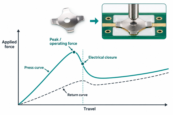
As the dome is pressed, applied force rises to a peak and then falls as it snaps. Electrical closure occurs when the conductive path meets the chosen test criterion; its exact position must be measured, not assumed to coincide with the peak. The release trace follows a different path, so the opening point can differ from the closing point.
Record force, displacement and electrical state on one time-aligned trace. Mark the peak, first qualifying closure, maximum allowed travel and release point. A clear tactile snap with closure too late in the stroke can leave little travel margin for a short actuator.
Why Can a Switch Click but Fail an Electrical Test?
A click proves that a mechanical element moved through its tactile transition; it does not prove a low-resistance path. An off-center actuator, contact-pad mismatch, contamination, an insulating surface film or a stop that limits travel can prevent stable electrical closure. A high-voltage continuity tester can also mask a marginal low-level contact by breaking through a film that the actual input circuit cannot clear.
Check the assembled key under the intended voltage and current conditions. If closure is intermittent, compare the force-travel trace with the electrical trace before changing dome force; the root cause may be the pad, finish or actuator rather than the spring.
How Does Dome Geometry Affect Force and Closure?
Dome outline, formed height, material thickness and heat treatment can change the force-displacement response. The PCB contact footprint and loading point then determine whether the dome closes the intended circuit at the required travel. A higher trip-force option does not automatically provide higher contact normal force or solve a poor pad layout.
For a four-leg metal dome, check the leg support and the intended contact path shown in the released drawing. Compare candidate domes in the same PCB and actuator stack; changing both the dome and the fixture in one trial makes the result hard to interpret.

How Do PCB Pads and Finish Affect the Contact?
The dome must bridge the intended conductors without resting on a solder-mask step or touching an unintended trace. Pad shape, copper thickness, surface finish and cleanliness influence where contact occurs and how consistently it repeats. Use the dome supplier’s matching footprint rather than scaling a generic drawing to a new dome diameter.
If the signal is very low current, specify the actual circuit conditions and evaluate contact resistance with a test that does not artificially improve the contact. Avoid assuming a plating change will compensate for a misplaced center pad or insufficient actuator travel.
What Changes When the Actuator Is Off-Center?
An off-center or tilted actuator can load one side of the dome before the other. The key may still click, but its measured peak, travel and electrical closure can vary by press location. A stiff overlay, thick spacer or housing tolerance can add further difference between a bare-dome test and the finished keypad.
Test center and worst-case edge presses at the intended keycap locations. Define the actuator tip diameter, lateral tolerance, stack height and mechanical stop. These inputs are more useful than specifying a nominal gf value alone.
How Do You Measure Force and Electrical Closure Together?
Use a controlled vertical probe on the assembled key while logging load and displacement. Connect the PCB contacts to an electrical measurement circuit with a stated voltage, current limit and closed-state threshold. Synchronize the channels so that first closure, stable closure, peak load and release can be located on one trace. Run multiple presses after any specified preconditioning, then compare the spread across samples and key positions.
Do not let a large probe bridge the PCB pads or touch the carrier outside the designed actuator region. If the intended button uses an overlay, test through that overlay; a bare-dome result is useful for incoming inspection but does not replace finished-assembly acceptance.
Which Test Conditions Must Be Specified?
Force values are only comparable when the test method is comparable. Put the following on the drawing or validation plan:
- Test state: bare dome, dome array on PCB, or fully assembled keypad.
- Probe tip size, press location, loading direction and speed.
- Force and travel units, tolerances, sample count and preconditioning cycles.
- Electrical test voltage, current limit, resistance or logic threshold, and debounce treatment.
- Operating temperature, contamination exposure and required life-test checkpoints when relevant.
The electrical threshold should reflect the real input circuit. A pass/fail rule based only on audible click or continuity at an unspecified meter setting is not repeatable procurement evidence.
How Do You Interpret Failed Force and Closure Results?
Separate a mechanical mismatch from an electrical contact problem before revising the dome tool.
| Test observation | Check first | Next action to evaluate |
|---|---|---|
| Peak force too high; closure otherwise stable | Dome specification, actuator leverage, overlay stiffness | Compare bare and assembled traces with the same probe |
| Peak force acceptable; closure late | Mechanical stop, travel allowance, pad alignment | Measure remaining stroke and correct the stack or footprint |
| Click occurs; closure intermittent | Contact finish, contamination, lateral alignment | Inspect contacts and repeat at the actual circuit level |
| Closure works at center but fails at edge | Actuator tilt, keycap guidance, PCB support | Test worst-case tolerance positions and revise guidance |
| Release is inconsistent | Return force, adhesive interference, overtravel damage | Inspect carrier clearance and repeat cycling |
Any single symptom can have more than one cause. A paired force/electrical trace makes the first corrective experiment narrower and keeps the next prototype informative.
What Should You Send for a Dome Design Review?
Provide the PCB contact drawing, dome outline and target force/travel range, keycap or overlay stack, actuator tip, available stroke, circuit voltage/current and required acceptance test. If several keys share a carrier, include center coordinates and the carrier drawing for a custom dome array. Mark the press locations that must work at tolerance extremes.
For a packaged tactile switch, ask its maker for the defined operating-force and electrical test conditions. For a metal-dome-on-PCB design, we can compare dome options against the actual assembly requirements rather than guessing a contact force from a catalog number.
FAQ
Is tactile switch contact force measured in gf or newtons?
External push force is commonly stated in gram-force or newtons; 1 N is about 102 gf. Contact normal force can use the same force units, but the number refers to a different location and must not be equated with the push-force rating.
Does a higher operating force always improve electrical contact?
No. It may change the mechanical response, but contact stability also depends on geometry, surface condition, alignment and available travel. Test the complete design at the intended electrical level.
Can a continuity meter verify contact force?
No. It can indicate closure under its own test conditions, but it cannot measure the local mechanical contact force. Pair a controlled force/displacement test with a defined electrical criterion.
Should a bare dome and finished keypad have the same force?
Not necessarily. The overlay, adhesive, spacer, actuator and housing can alter the external force measured at the key surface. Specify which assembly state the acceptance value applies to.
For tactile switch contact force, the useful purchase specification is a defined operating-force test plus measured electrical closure in the finished assembly. EBest Circuit(Best Technology) can review your dome drawing, PCB pads and actuator stack for a metal-dome prototype. Send the files and target quantity to sales@metal-domes.com.