Dome sheets for smart card readers are pre-positioned tactile metal domes carried on adhesive PET film and aligned with the keypad contacts of a reader, payment terminal or access-control device. The sheet is part of the terminal’s button interface; it is not installed inside the plastic smart card. A reliable design coordinates the dome, carrier, PCB or FPC contacts, actuator, adhesive, vent path and enclosure support as one assembly.

This guide is for product engineers and buyers developing a smart card reader with keypad input. It explains which drawing inputs control key feel and contact reliability, where application-specific validation is required, and what we need to review before samples or a quotation.
What Are Dome Sheets for Smart Card Readers?
A dome sheet, also called a metal dome array or tactile dome sheet, retains multiple snap domes at fixed coordinates on a thin PET or Mylar carrier. Pressure-sensitive adhesive bonds the carrier to a PCB, FPC or membrane circuit. When a user presses a key, the dome collapses, bridges the outer and center contacts, and returns when the load is released.
The phrase smart card keypad can describe several products: a payment terminal, door-access reader, identity reader or handheld authentication device. In each case, the dome sheet belongs to the reader’s user interface. The card, antenna, secure element and reader electronics perform different functions and should not be confused with the tactile switch layer.
Where Does the Dome Sheet Fit in the Reader Assembly?
The dome sheet sits between the key actuator or overlay and the circuit contacts. Its exact position depends on whether the product uses molded keys, a membrane overlay or a rigid keypad bezel. The housing must support the PCB beneath the keys so that panel flex does not absorb actuation force.
| Assembly element | Primary function | Critical interface |
|---|---|---|
| Keycap or graphic overlay | Transfers the user’s load and identifies the key | Actuator diameter, centering and overtravel |
| PET dome sheet | Retains and registers the metal domes | Carrier outline, adhesive land, venting and alignment holes |
| Metal dome | Provides tactile snap and momentary contact | Force, travel, size, plating and pad match |
| PCB, FPC or membrane circuit | Provides the outer and center contacts | Pad geometry, flatness, finish and cleanliness |
| Housing support | Maintains mechanical reaction force | Local stiffness, ribs, fasteners and clearance |
Review the whole stack before fixing a dome force. A dome measured by itself can feel different after the overlay, adhesive, actuator and enclosure are added.
How Is a Smart Card Keypad Dome Sheet Constructed?
A basic construction uses formed stainless-steel domes under an adhesive PET carrier and a removable release liner. A multi-layer design can add a spacer that defines the dome cavity, controlled air channels, printed conductive shielding, a compliant bonding layer or small plungers above the dome crowns.
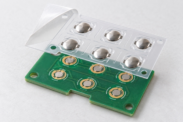
The carrier is not merely packaging. Its die-cut profile, registration holes, adhesive openings and vent geometry determine how accurately the domes remain over the circuit during assembly and use. A custom dome array can follow the reader outline, key pitch, component clearances and alignment features shown in the customer’s drawing.
How Should Dome Positions Align With PCB or FPC Contacts?
Each dome center, pad center and actuator center should share one coordinate system. The drawing must define the origin, datum holes, key pitch, array outline and allowed registration error. If these elements are dimensioned from different references, the worst-case stack can load the dome off-center or leave it partly outside the contact pattern.
The PCB or FPC contact normally separates a center pad from an outer contact. The dome rests on the outer region and touches the center when collapsed. Solder-mask steps, exposed vias, contamination, uneven surface finish or flexing beneath the dome can produce unstable seating. Keep routing features and mask edges out of the mechanical contact area unless the structure has been specifically reviewed.
Assembly aids should be functional. Tooling holes, outline tabs and a controlled release-liner peel direction can reduce skew during placement. Optical marks are useful only when the assembly process can actually see and use them.
Which Dome Force and Travel Suit Numeric and Function Keys?
Force is selected from the complete user interaction, not from a keypad category alone. A payment or access reader may be operated with bare fingers, gloves or a stylus-like key shape. Numeric keys may favor consistent repeated entry, while confirm, cancel or alarm-related functions may need clearer differentiation. The required tactile response should therefore be stated by key group.
- Define target trip force, tolerance, travel and click ratio for the assembled keypad.
- Identify keys that require a different force or geometry rather than assuming one dome for the whole sheet.
- State maximum allowed overtravel and the mechanical stop that controls it.
- Evaluate audible feedback separately from tactile feedback if noise matters.
- Measure representative corner, center and high-duty keys after final assembly.
For applicable dome-array structures, our published manufacturing range includes approximately 100-400 gf force, 0.13-0.30 mm travel and greater than 30% click ratio. These ranges describe manufacturing capability; the correct target still depends on the reader’s actuator, overlay and support structure.
When Should You Use a Single-Layer or Double-Layer Dome Array?
A single-layer metal dome array uses the adhesive carrier to retain the domes directly. It offers the lowest part count and can suit a compact reader when the circuit and housing already provide adequate clearance and a reliable air path.
A double-layer metal dome array adds a spacer beneath the domes. The spacer defines the cavities and can route air between keys or toward a controlled internal vent. It also helps isolate the dome edges from the circuit surface and can add dust protection within the keypad stack.
The double-layer option is not automatically better. It adds thickness and more die-cut interfaces. Choose it when its defined cavity, venting or protection solves a real assembly requirement; otherwise a correctly engineered single-layer carrier may be sufficient.
How Do Actuators and Overlays Change the Key Feel?
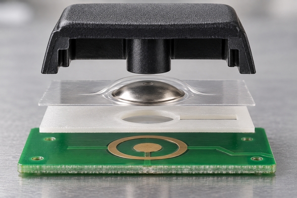
The actuator should load the dome crown near its center and remain aligned throughout the permitted key motion. A narrow or off-center boss can concentrate stress and make the snap inconsistent. A broad actuator may interfere with the dome edge or adjacent keys. Keycap tilt, bezel clearance and housing ribs also affect the force path.
When the key geometry cannot deliver a predictable load, a plunger dome array adds a controlled actuator to the PET carrier. We can evaluate plunger diameter, height and overall stack against the selected dome. Our published plunger capability is approximately 0.8-3.2 mm in diameter and 0.1-0.40 mm in added height, subject to the dome and project review.
How Should Adhesive, Venting and Sealing Be Balanced?
Adhesive holds the array in position, while venting allows air to leave and re-enter each dome cavity during actuation. Covering the cavity without an air path can make a key feel slow, heavy or inconsistent. Cutting a direct opening to the outside can create an ingress path. The design must preserve both internal airflow and the reader’s environmental boundary.
Specify the substrate material and surface energy, available adhesive land, operating temperature, humidity, cleaner exposure and expected assembly pressure. A narrow adhesive wall can lift or creep; an oversized adhesive opening can reduce dome support. The vent channel must also remain open after die cutting and lamination.
Where a compliant bond is needed between a molded keypad layer and the array, a rubber-glue dome array can be evaluated. It does not by itself make the complete reader waterproof. Perimeter sealing, card-slot geometry, display windows, cable entry and enclosure joints still require system-level design and testing.
What ESD, EMI and Grounding Details Matter?
Smart-card readers are touched frequently and may share an enclosure with displays, radios, power converters or long cable paths. If the project requires a shielding layer, the drawing must show where that layer terminates and how it connects to chassis or circuit ground. An unconnected conductive print is not a complete ESD strategy.
Our EMI metal dome array can add silver or silver-carbon printing to single- or double-layer constructions. The sheet, conductive path, grounding contact and enclosure must be reviewed together. Device-level payment, access-control or EMC compliance remains a responsibility of the complete terminal design; the dome sheet alone cannot establish certification.
Which Manufacturing Controls Prevent Key-to-Key Variation?
Consistency depends on both the components and their relative position. Inspection should cover the dome part number, carrier outline, adhesive openings, dome coordinates, vent continuity, release-liner condition and surface cleanliness. Sampling only one center key can miss edge-placement or lamination problems.
| Control item | Why it matters | Verification approach |
|---|---|---|
| Dome identity and orientation | Wrong geometry changes force, travel or contact behavior | Incoming lot and first-piece comparison |
| Array-to-pad registration | Misalignment creates uneven loading or intermittent contact | Datum-based dimensional inspection |
| Carrier and spacer cut quality | Burrs or shifted openings restrict motion and airflow | Optical inspection and section review |
| Adhesive coverage | Voids, contamination or lift can move the dome | Peel-liner and lamination inspection |
| Key force distribution | Readers require consistent repeated input | Trip and return-force sampling across the layout |
For applicable dome-array structures, we support dimensional tolerances of approximately +/-0.05 to +/-0.15 mm, force tolerance around +/-25 gf and life above 1,000,000 cycles. Final drawing tolerances and test limits must be matched to the selected materials, dome geometry and array construction.
What Should a Prototype Prove Before Reader Production?

A useful prototype uses the production-intent PCB or FPC, carrier, adhesive, actuator and housing support. A loose dome clicked by hand does not prove the finished reader interface.
- Confirm every key’s electrical make-and-break behavior with the real firmware scan logic.
- Measure trip force, return force and travel on center, corner and high-duty keys.
- Check rapid repeated entry and simultaneous adjacent-key use where the firmware permits it.
- Inspect the array after assembly for skew, trapped debris, liner residue and blocked vents.
- Run life cycling on the highest-use numeric and confirmation keys, then remeasure contact and force.
- Test temperature, humidity, cleaning agents, ingress and ESD in the complete reader configuration when required.
- Verify that card insertion, display operation and enclosure loading do not distort the keypad support.
We can provide trip-force, rebound-force and life-cycle test support for metal domes and dome arrays. The validation plan should still be tied to the customer’s reader specification and acceptance criteria.
What Information Should Be Included in the RFQ?
A dome-sheet quotation is more accurate when the mechanical and electrical interfaces are visible. Send the following information with the inquiry:
- 2D drawing, CAD, Gerber, PCB/CAM file or dimensioned sample with one coordinate origin.
- Reader type, key count, key pitch, array outline, cutouts and alignment-hole locations.
- PCB or FPC contact-pad drawing, surface finish and support condition.
- Target trip force, travel, click ratio, sound and any mixed-force key groups.
- Overlay, molded key or plunger geometry, including permitted overtravel.
- Adhesive surface, operating environment, cleaner exposure and sealing target.
- ESD, EMI, grounding, life-cycle and other validation requirements.
- Prototype quantity, annual demand, packaging preference and production schedule.
These inputs allow us to identify whether the project needs a single-layer, double-layer, plunger, rubber-glue or EMI structure before samples are released. Missing values can be marked for engineering review instead of being replaced by assumptions.
How Can We Support a Smart Card Reader Dome Sheet?
At EBest Circuit(Best Technology), we have manufactured metal domes and metal dome arrays since 2006. We can arrange different dome sizes, shapes and forces on one custom carrier; support PCB, FPC and membrane-switch assemblies; and work from CAD, PDF, Gerber, PCB/CAM files or customer drawings. For suitable dome-array constructions, our total-height capability is approximately 0.28-0.45 mm, subject to the selected stack and engineering review.
For a dome sheets for smart card reader project, send the keypad layout, contact drawing, actuator stack, environment, validation requirements and forecast to request a manufacturing review and quotation. We will confirm the open engineering inputs before recommending the array structure.