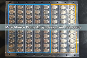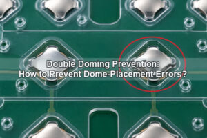

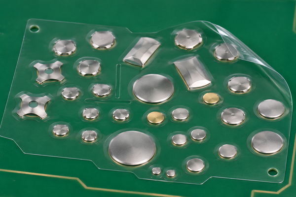
A mixed-size dome array places metal domes with different diameters, footprints or shapes on one adhesive carrier. The drawing must match every dome position to its PCB contact pad, actuator, adhesive pocket and vent path. A single carrier can simplify installation, but only when each key is treated as a separate mechanical and electrical station rather than as a scaled copy of the next key.
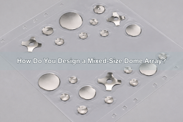
What Is a Mixed-Size Dome Array?
It is a custom metal dome array in which the bill of materials changes by key position. One position may use a small round snap dome, another a larger round dome, and another a four-leg or triangle dome. The PET carrier keeps those parts registered as one assembly for placement on a PCB, membrane circuit or FPC.

Different dome sizes are not selected for appearance. Each change affects the footprint, support perimeter, contact area, available actuator diameter and spacing around adjacent keys. Our released array drawing therefore identifies the dome part number, orientation and carrier opening for every key ID.
When Should One Array Use Different Dome Sizes?
Use mixed dome sizes when the interface contains physically different controls. A large navigation key may have a wider keycap and contact area, while compact side keys must fit inside a narrow bezel. A four-leg dome can suit a pad layout that needs defined support points, while a round dome may fit a compact circular contact pattern.
- Different keycap diameters or actuator footprints
- Unequal space around display windows, connectors or enclosure ribs
- Different PCB contact-pad geometries on the same interface
- A combination of round, four-leg, triangle or oblong key stations
- Legacy layouts that must consolidate several loose dome types into one carrier
If every key has the same contact geometry and mechanical stack, a uniform dome array is usually easier to release and inspect. Mixed sizing should solve a real layout or actuation requirement, not add unnecessary part variation.
Mixed-Size Dome Array vs Mixed-Force Dome Array
| Array type | Primary difference | Drawing focus | Acceptance focus |
|---|---|---|---|
| Mixed-size dome array | Diameter, footprint, shape or height changes by position | Pad geometry, pocket outline, spacing, actuator size and registration | Correct geometry at every key and stable placement |
| Mixed-force dome array | Specified trip force changes by position | Force class or part number assigned to each key | Measured force and tactile separation in the assembled keypad |
| Mixed-size and mixed-force array | Geometry and force both change | Position-specific part number plus full mechanical stack | Geometry, installed force, electrical closure and return at each key |
Dome diameter can influence force, but it does not define force by itself. Material thickness, forming geometry, shape and supplier process also matter. If both size and force vary, the drawing must state both requirements instead of assuming the larger dome is automatically firmer.
How Do Dome Diameter and Shape Change the Contact Area?
The dome perimeter must rest on the intended outer contact or support area while the center region closes the switching path. A larger dome needs a larger supported footprint and usually a larger clear area around the moving center. A four-leg or triangle dome transfers load through defined legs, so its orientation matters as well as its nominal diameter.
| Dome family | Published size range | Published force range | Mixed-array design check |
|---|---|---|---|
| Round metal dome | 3–16 mm diameter | 100–600 g | Confirm full perimeter support and center-contact clearance |
| Four-leg metal dome | 5–20 mm diameter | 100–600 g | Match leg orientation and support points to the pad pattern |
| Triangle metal dome | 4–15 mm diameter | 100–800 g standard range | Define rotational orientation and leg clearance |
These are our published product-page ranges, not an instruction to combine any three sizes in one stack. We confirm the exact orderable dome and prototype behavior against the customer drawing.

How Should PCB Contact Pads Match Different Dome Sizes?
Each key station needs its own pad geometry. The outer contact must support the selected dome without entering the moving center, and the inner contact must be reached consistently after snap-through. Simply scaling one pad pattern can fail when the next dome uses legs, a different dimple or a different contact path.
Release the PCB and array from the same coordinate system. For every key ID, record the dome part number, pad drawing reference, contact finish, center coordinate and orientation. Keep solder mask, exposed copper, vias and nearby components outside the dome movement and adhesive sealing zones.
How Much Spacing Is Needed Between Unequal Domes?
Spacing is controlled by more than edge-to-edge dome clearance. The carrier needs enough land for adhesive sealing, kiss-cutting and handling. The PCB needs routing space and electrical clearance. The enclosure needs room for independent actuators without side-loading the neighboring key.
Measure from the actual dome and pocket outlines, not from key-center pitch alone. A large dome placed beside a small dome creates an asymmetric adhesive land; the narrow side may become the limiting feature. Our drawing review checks the smallest remaining web, the cutting path, adjacent actuator envelopes and whether vent channels weaken that area.
How Should the Adhesive Carrier Be Designed?
The carrier must hold every dome in its assigned position through shipping, liner removal and final lamination. Pocket outlines should follow the selected dome geometry without trapping a leg, covering the active center or leaving an unsupported edge. The release liner and pull direction also matter when the array contains both very small and much larger domes.
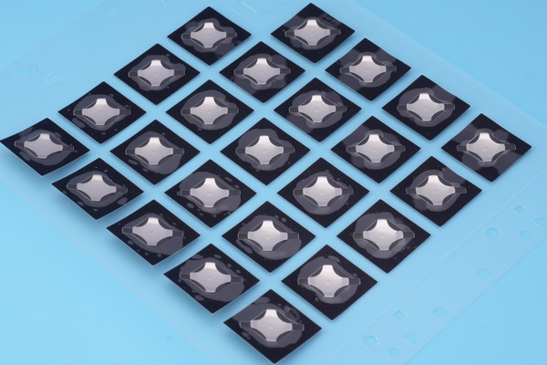
Our single- and double-layer dome arrays can place different domes on one array according to the customer design. A single-layer construction uses adhesive PET to retain the domes. A double-layer construction adds a spacer and air paths, which can protect the film and provide a controlled route for displaced air.
How Do Vent Paths Change Across Dome Sizes?
Every dome displaces air when it collapses and returns. A larger dome generally encloses a different air volume than a smaller dome, so the same narrow route should not be copied blindly across all positions. The path must reach a safe endpoint without crossing exposed contacts, adhesive sealing lands or contamination-sensitive areas.
For a single-layer array, an individual air hole may be used at each key. In a double-layer array, channels can connect dome pockets to an outlet. We review the route with the customer enclosure because a channel that ends under a gasket or a fully compressed housing rib is not a usable vent.
How Should Actuators Match Different Dome Heights?
Actuator diameter should load the intended central region without catching a leg or pushing near the perimeter. When dome sizes or shapes differ, the actuator geometry may also need to change by key. A single oversized plunger can work on the larger dome but create off-center loading on a smaller neighbor.
Height differences must be handled in the complete stack. Keycap height, overlay thickness, spacer, adhesive, dome free height and enclosure datum all contribute to preload and over-travel. We ask for the actuator drawing or keypad section so the prototype can be checked as an assembly, not only as a loose dome sheet.
Can Different Dome Shapes Share One Array?
Yes, provided each shape has a compatible PCB pad, carrier pocket and actuator. Round, four-leg, triangle and oblong domes can solve different space and contact-layout constraints. Shape mixing is practical when the interface genuinely contains different key geometries.
Do not rotate a legged dome merely to fit the carrier cut. Its legs must land on the designed support and contact regions. Put an orientation mark or angle on the array drawing and define which feature establishes zero degrees. That prevents an apparently centered part from being electrically or mechanically wrong.
How Do You Control Placement Tolerance and Registration?
Use common datums for the PCB, carrier and enclosure. Two widely separated tooling holes or edge features help control translation and rotation. Key-center coordinates should be dimensioned from those datums, while local pocket dimensions control each dome inside the carrier.
Small domes can expose registration error sooner because their pad and actuator windows are smaller. Large domes can amplify carrier distortion over a wider footprint. During prototype review, we inspect pocket centering, leg orientation, liner removal behavior and the position of the completed array on the board.
How Should a Mixed-Size Dome Array Be Tested?
Test every key ID rather than sampling only one representative dome. The array may contain several mechanical constructions, so acceptance should preserve position-level traceability.
| Test | What it confirms | Mixed-size risk it detects |
|---|---|---|
| Visual and dimensional inspection | Correct dome, pocket, orientation and location | Wrong size or rotated legged dome |
| Electrical continuity during actuation | Reliable contact closure at each key | Pad mismatch or off-center loading |
| Force-displacement check | Installed tactile response and return | Unintended preload, over-travel or height mismatch |
| Repeated actuation | Carrier retention and stable switching | Pocket damage, dome migration or adhesive lift |
| Fit check in the enclosure | Actuator alignment and available travel | Neighbor interference or blocked vent route |
The acceptance record should link each result to the key ID and installed dome part number. If the same size appears at several locations, compare those positions for systematic actuator or board-support differences.
Mixed-Size Dome Array FAQs
Can one dome array contain different dome sizes and shapes?
Yes. We can position different domes on one custom carrier when each position has a defined dome, pad pattern, pocket and orientation. Prototype approval is required before volume production.
Does a larger dome always have a higher actuation force?
No. Diameter is only one input. Shape, material thickness and formed geometry also influence force. Specify the required force or exact part number separately from size.
Can the same actuator be used for every dome?
Only if its diameter, position and travel suit every dome station. When the array mixes small round domes with larger or legged domes, position-specific actuator geometry may be necessary.
Is a mixed-size array harder to assemble than loose domes?
The completed carrier can reduce placement steps because all keys transfer together. The engineering work moves upstream into the drawing, pocket design, tooling and prototype validation.
What Should You Include in a Mixed-Size Dome Array RFQ?
Send us the PCB contact drawing, array outline, key-center coordinates, dome size or candidate part number for every position, actuator section, target force, expected life, operating environment and annual quantity. Identify any keys that need gold plating, dimples, center holes, special venting or a different carrier stack.
A position table prevents ambiguity:
| Required RFQ field | Example content | Why we need it |
|---|---|---|
| Key ID and coordinate | K1 at X/Y from datum A/B | Controls position and registration |
| Dome requirement | Shape, diameter, force or approved part number | Locks the position-specific bill of materials |
| PCB pad drawing | Exposed contacts, finish and keep-outs | Confirms mechanical support and electrical closure |
| Actuator stack | Keycap diameter, preload and available travel | Checks alignment, height and over-travel |
| Carrier and environment | Single/double layer, vent endpoint, temperature and sealing needs | Defines adhesive and air-path requirements |
At EBest Circuit(Best Technology), we use these inputs to review the mixed-size dome array as one controlled assembly and return a manufacturable proposal instead of guessing at dome substitutions from a keypad image.