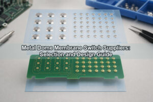
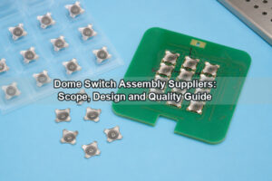
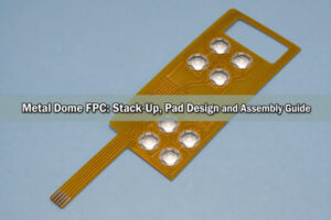
A peel-and-place tactile dome array holds tactile metal domes at controlled coordinates on a carrier so the complete pattern can be transferred to a PCB, FPC or membrane-switch circuit in one aligned operation. The format reduces loose-dome handling, but reliable results still depend on pad geometry, venting, adhesive selection, registration features, actuator alignment and a controlled application process.

What Is a Peel-and-Place Tactile Dome Array?
It is a pre-arranged set of tactile metal domes retained by a PET or similar carrier and protected by a release liner. Each dome remains at its specified X-Y position until the liner is removed and the carrier is laminated to the target circuit. The array may contain one dome, a repeated keypad matrix or mixed dome sizes and forces for a custom interface.

This article focuses on selection, transfer and verification. Readers who only need the basic peel-and-place dome array definition can start with that overview; the sections below address the engineering details that determine whether the assembly will work consistently.
How Does the Peel-and-Place Structure Work?
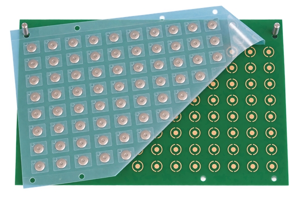
The removable liner protects the adhesive before assembly. After the liner is peeled away, the carrier keeps every dome located over its contact pattern while the adhesive bonds to the circuit surface. The metal dome remains free to collapse under an actuator and return after release, while the carrier limits lateral movement and protects the switching area from handling.
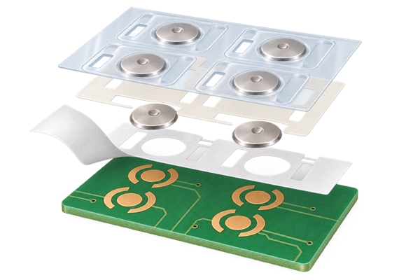
A typical stack may include a top carrier, pressure-sensitive adhesive, tactile domes and a release liner. The exact construction is project-specific. Vent paths, adhesive openings and spacer features must be designed around dome travel rather than treated as decorative cutouts.
When Is Peel-and-Place Better Than Loose Domes?
The format is most useful when a keypad contains several switch positions, the pitch is tight, manual placement is difficult or the customer wants a repeatable transfer step. A peel-and-place metal dome format can reduce individual handling and help maintain orientation during assembly.
Loose domes may still be reasonable for a very small quantity, a single service replacement or a process that already uses dedicated placement equipment. Peel-and-place does not automatically solve a poor pad layout, a contaminated bonding surface or an actuator that contacts the dome off center.
What Information Defines the Dome Layout?
A production drawing should define the array outline, datum system, dome center coordinates, pitch, registration holes, carrier edge clearances and the orientation of every non-circular dome. The dome specification should identify shape, diameter or envelope, trip force, return force when required, travel, height, dimple option and finish.
For a mixed keypad, the drawing must show which positions use different forces or geometries. Our custom dome array review can work from CAD, PDF, Gerber, PCB/CAM files or customer drawings. We confirm the manufacturable carrier outline and positioning method before production rather than assuming the visual layout is sufficient.
How Should PCB Contact Pads and Vent Paths Be Prepared?
Each switch position needs a center contact electrically isolated from the outer contact area. The dome bridges these contacts only when it collapses. Copper spacing, surface finish, solder-mask clearance and contamination control all influence electrical consistency. A center hole must not be added to the dome unless the pad and actuation design were developed for that construction.
Air must escape when the dome is pressed. A vent can be routed through the circuit, within a spacer channel or toward the array edge. The selected path must stay open after lamination. Trapped air can increase actuation force, slow return or create an inconsistent tactile response.
How Do You Align and Apply the Array?
Use a clean, flat fixture or stable work surface. Do not touch the exposed adhesive or dome contact surfaces. A controlled process normally follows this sequence:
- Clean and dry the PCB, FPC or membrane circuit according to the approved assembly process.
- Confirm the part number, orientation mark and datum features against the drawing.
- Locate the carrier with registration holes, tooling pins or clearly defined board edges.
- Peel the release liner back gradually at a low angle instead of removing it before alignment.
- Apply the carrier from the datum side outward with even pressure, avoiding wrinkles and trapped air.
- Inspect every dome position before installing the overlay or actuator layer.
What Adhesive and Carrier Requirements Matter?
The adhesive must hold the carrier through assembly and service without flowing into the active dome area. Selection depends on the bonding surface, temperature range, humidity, chemicals, surface energy and expected life. Adhesive openings must leave the dome free to move and keep vent paths open.
Carrier thickness affects total stack height, handling and local stiffness. The carrier must be flexible enough to laminate without bridging yet stable enough to preserve the dome coordinates. Our published array options include King Label, 3M 467 and 3M 468 adhesives for selected constructions, but the final choice remains subject to substrate, environment and engineering review.
How Do Actuator Geometry and Overlay Stack-Up Affect Tactile Feel?
The actuator should load the intended dome region without excessive side force. An undersized, tilted or laterally offset actuator can distort the force curve and accelerate wear. The overlay, spacer, plunger and housing must provide enough clearance for dome travel and return.
Trip force alone does not define perceived feel. Return force, click ratio, travel, actuator stiffness and overlay preload all contribute. For applications needing a defined force-transfer element, a plunger-style array may be more suitable than a plain carrier, but it should be chosen as part of the complete interface stack.
What Assembly Defects Should Be Prevented?
| Defect | Likely cause | Control action |
|---|---|---|
| Dome shifted from pad center | Weak datum, carrier stretch or early adhesive contact | Use tooling features and peel the liner progressively |
| High or inconsistent actuation force | Blocked vent, overlay preload or off-center actuator | Verify the vent path and complete stack-up |
| Intermittent electrical contact | Contamination, pad geometry or surface-finish issue | Control cleaning and inspect contact dimensions |
| Carrier lifting | Low surface energy, moisture, dust or unsuitable adhesive | Qualify the adhesive and surface preparation |
| Slow dome return | Trapped air, excessive preload or adhesive intrusion | Open the vent and restore dome clearance |
These defects are linked. For example, a shifted carrier can place the actuator off center and partially cover a vent at the same time. Inspection should therefore compare the installed assembly with the released drawing, not check only whether the sheet appears attached.
How Should the Installed Array Be Inspected and Tested?
Visual inspection should verify orientation, registration, carrier adhesion, dome centering, vent continuity and absence of wrinkles or foreign material. Dimensional sampling should reference the same datums used on the drawing. Electrical continuity and actuation checks should cover every switch position.
Functional evaluation should measure more than initial closure. Depending on the program, it may include trip force, rebound force, travel, resistance, repeated actuation and environmental conditioning. We provide trip-force, rebound-force and life-cycle testing for applicable projects. Published dome-array life can exceed 1,000,000 cycles, but actual performance depends on dome geometry, array stack-up, actuator, circuit layout, environment and the agreed test method.
How Do Single-Key Pieces Differ from Multi-Key Arrays?
A single-key dome array is an individual kiss-cut carrier piece containing one dome. It is useful for selective placement, prototypes, repair work or products with isolated switch positions. A multi-key array transfers an entire keypad pattern and is normally more efficient when all switch locations share one assembly step.
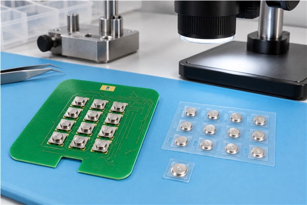
The correct format depends on product architecture and process flow. Single-key pieces increase placement count but allow local flexibility. A full metal dome array improves pattern-level handling but requires the carrier outline, registration method and circuit geometry to be coordinated from the start.
What Information Should Be Supplied for Engineering Review?
Provide the PCB, FPC or membrane-circuit drawing together with the dome coordinate file and mechanical stack-up. The project package should identify target force, travel, height, dome shape and size, adhesive preference, operating environment, expected life, annual quantity, prototype quantity and test requirements.
- Final circuit contact-pad dimensions and surface finish
- Array datum, registration holes and orientation marks
- Overlay, actuator or plunger dimensions above each dome
- Vent path and sealing requirements
- Required delivery format and assembly method
- Acceptance limits for force, dimensions and electrical response
Missing stack-up information often creates more risk than a missing cosmetic dimension because the same dome can feel different under a different actuator or preload.
How Can EBest Circuit Support Your Dome Array Project?
EBest Circuit(Best Technology) has manufactured metal domes and metal dome arrays since 2006. We supply single-layer, double-layer, EMI-printed, rubber-glue, LGF, single-key, plunger and custom array constructions. Our peel-and-place tactile dome array support covers PCB, FPC and membrane switch assembly, with dome geometry, force, travel, carrier, adhesive and registration reviewed as one system.
Published dome-array capabilities include travel from 0.13 to 0.30 mm, force from 100 to 400 gf and force tolerance of ±25 gf for applicable constructions. These are portfolio ranges, not universal promises; final capability depends on dome geometry, stack-up, adhesive, circuit layout, environment, order quantity, test method and engineering review. Send your drawing and assembly requirements to sales@metal-domes.com or contact our engineering team for a manufacturability review.