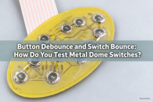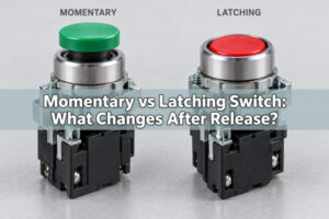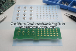

A dome switch for electrical switch applications is a low-profile momentary contact that combines electrical closure with a tactile snap. The dome is only one part of the finished switch: the PCB contact pattern, actuator, retention method, vent path and enclosure determine whether it closes reliably and feels consistent. This guide explains how to select and integrate the metal dome as an electrical switching element, not as a vehicle dome-light switch or a complete packaged pushbutton.
What Is a Dome Switch for Electrical Switch Applications?
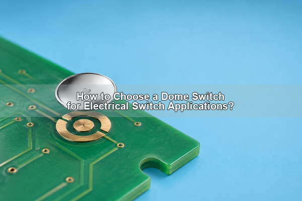
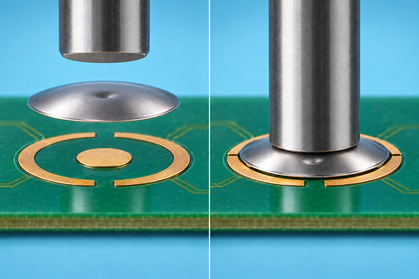
In an electronic control interface, a dome switch is a formed spring contact placed over two electrically isolated PCB or FPC conductors. Its perimeter is supported by the outer contact. When a centered actuator reaches the trip force, the crown snaps downward and bridges the center contact to the outer circuit. Releasing the actuator lets the dome recover and reopen the circuit.

The metal dome therefore performs two jobs: it is the moving conductor and the tactile spring. It is not a complete switch by itself. A complete dome switch assembly also needs controlled positioning, a compatible contact pattern, an actuator and protection from contamination. Our dome switch button overview provides the basic component definition; this article focuses on system selection and integration.
How Does a Metal Dome Close the Circuit?
At rest, the center pad remains electrically open. As the actuator loads the dome, force rises until the geometry becomes unstable. The dome then snaps through, its center touches the center pad and current can pass between the center and outer contacts. This force drop is the tactile event felt by the user.
Electrical closure and tactile sensation are related but not identical. The contact can close before the visible key reaches its mechanical stop, and continued travel can over-stress the dome if the housing does not limit over-travel. The switch circuit should therefore be validated with the production actuator and enclosure rather than with the loose component alone.
Is a Dome Switch Normally Open or Normally Closed?
Most metal dome switch designs are SPST, normally open contacts. No current path exists between the center and outer pad until the dome is pressed. This behavior suits user-interface commands such as power, reset, pairing, mode selection and menu navigation, where one press creates one momentary input.
Do not assume that every product called a dome switch has the same circuit. Rubber keypads can use conductive pills, membrane circuits can use printed contacts, and packaged switches can contain different internal contact arrangements. If a system needs a normally closed signal, maintained action or power switching, use an architecture designed for that function instead of treating a standard snap dome as a substitute.
Metal Dome vs Rubber Dome vs Polydome
The correct choice depends on which layer provides spring action, which layer carries current and how much profile and tactile definition the product needs.
| Switch element | Spring and contact method | Typical advantage | Main design boundary |
|---|---|---|---|
| Metal dome | Formed metal spring bridges PCB or FPC contacts | Crisp snap, low profile and direct electrical contact | Needs accurate pad, actuator, retention and vent design |
| Rubber dome | Elastomer web returns the key; a conductive pill or circuit contact may close the switch | Integrated key structure, sealing options and softer feel | Feel depends strongly on rubber geometry and aging |
| Polydome | Thermoformed polyester provides snap action; conductive ink forms the contact | Very thin printed switch construction | Force range, resistance and life must match the printed structure |
| Packaged tact switch | Housing contains the spring and terminals | Defined component package and standard assembly route | Greater height and footprint than a bare-dome interface |
A membrane switch can contain a metal dome, so “metal dome vs membrane” is not always a true either-or comparison. The membrane may be the carrier, graphic layer or sealed circuit around the metal switching element.
Which Delivery Format Fits the Assembly?
Delivery format determines who controls dome placement, retention and production handling. Select it together with the assembly process, not after the PCB and enclosure are frozen.
| Format | Best fit | Responsibility that remains with the product design |
|---|---|---|
| Loose metal dome | One key, widely separated keys, prototypes or dedicated placement fixtures | Individual alignment, retention, cleanliness and venting |
| Single-key adhesive carrier | Independent key that needs easier placement | Carrier outline, adhesive window and local datum |
| Metal dome array | Several keys that need shared registration and lamination | Array outline, vent channels, adhesive zones and PCB datum |
| SMD dome switch | Automated pick-and-place and reflow assembly | Land pattern, reflow profile, package clearance and wash process |
| Packaged tact switch | Standard discrete switch footprint and enclosure clearance | PCB footprint, soldering and actuator-to-package interface |
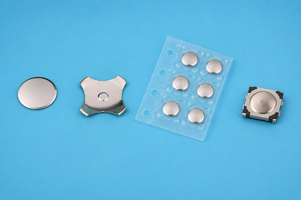
For multiple registered keys, a custom metal dome array can locate different dome sizes and force options on one carrier. For solderable automated assembly, an SMD dome switch should be evaluated as a package with its own land pattern and process limits. A standalone dome switch remains useful when the housing or fixture can control a single loose dome.
Which Dome Shape and Force Should You Choose?
Start with the available contact footprint, actuator diameter, desired trip force, target travel and production method. A circle metal dome fits compact centered keys and uses space efficiently. A four-leg metal dome provides defined support points and open regions between the legs that can support trace and vent routing.
Triangle domes can support high-force or constrained layouts, while oblong domes suit narrow keys. These shapes are not drop-in substitutes because the support perimeter and pad geometry change with the outline. Our published metal-dome range covers multiple shapes and force levels, but the usable specification must be confirmed for the selected series, size, plating and application.
Nominal trip force alone does not predict finished key feel. Compare trip force, return force, click ratio, travel and height on the same force-displacement curve. A high click ratio gives a more distinct drop after actuation, while insufficient return force can make recovery more sensitive to overlay stiffness or preload.
How Should the PCB Contact Pattern Be Designed?
The center pad must remain electrically isolated from the outer contact until the dome collapses. The outer contact should support the selected dome evenly. Avoid exposed vias, solder-mask ridges, silkscreen, surface steps or debris in the seating and contact areas. A local board deflection can absorb dome travel and make the key feel soft even when the loose dome meets its force target.
Pad diameter, center clearance and outer-ring width must follow the actual dome drawing. Surface finish should be flat, clean and compatible with the specified contact-resistance target. Do not scale a footprint from a product photograph or reuse the same land pattern for different dome shapes.
How Do Actuator Alignment, Preload and Venting Affect Performance?
The actuator should load the dome near its center and stay centered through the key stroke. An off-axis tip can tilt the dome, load one edge first and change both force and contact timing. The actuator diameter must be large enough to avoid a sharp local stress but small enough to stay clear of the dome support region.
Preload removes free play, but excessive preload reduces available travel and can leave the dome partially stressed. The housing should also provide a hard stop so user over-travel is not absorbed entirely by the metal spring.
Each press changes the air volume beneath the dome. Provide a deliberate vent path through the spacer, between dome legs or through another controlled channel. A sealed cavity can slow return or change tactile force; an uncontrolled opening can direct particles and moisture toward the contact.
What Electrical Ratings Must Be Checked?
A dome switch is normally used as a low-current signal input, not as a power contact. Our published C, F, T and O series specifications list a maximum of 12 mA at 24 V DC, but the selected part drawing and application conditions remain the controlling requirements. Loads outside the specified range can increase arcing, contamination sensitivity and contact wear.
| Rating or characteristic | Why it matters in the finished switch |
|---|---|
| Contact configuration | Confirms the expected normally open momentary circuit |
| Voltage and current | Prevents a signal contact from being used as a power switch |
| Contact resistance | Must match the sensing circuit, plating and measurement method |
| Contact bounce | Determines whether hardware or firmware debouncing is required |
| Insulation and breakdown | Protects spacing between isolated conductors |
| Operating environment | Defines temperature, humidity and contamination exposure for validation |
Plating may reduce contact resistance or improve performance in a defined environment, but it does not correct a poor pad surface, excessive current or contamination. Confirm the resistance limit, test load and acceptance method instead of comparing one headline number.
Where Are Dome Switches Used?
Metal dome switches suit compact interfaces that need a short momentary electrical signal and a perceptible tactile event. Common examples include handheld instruments, medical-device controls, automotive interior buttons, industrial panels, remote controls, access devices, appliance controls and service or reset keys on electronic equipment.
The application name does not determine the dome by itself. A handheld instrument may prioritize low profile and light force, while an industrial control may need stronger resistance to accidental operation. Automotive and medical projects can add tighter requirements for temperature, contamination, traceability and validation. The selected dome, contact finish, carrier and enclosure must be reviewed as one switch system.
What Should Be Tested Before Production?
First verify the loose component against its drawing, then test the complete dome switch assembly. A production-representative sample should use the intended PCB finish, adhesive or carrier, actuator, housing, vent route and firmware debounce settings.
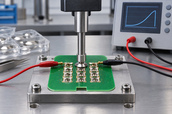
- Measure trip force, return force, travel and force-displacement consistency.
- Verify electrical closure, contact resistance and bounce with the intended sensing circuit.
- Test centered, off-center and edge presses on the visible key.
- Inspect dome position, carrier registration, adhesive intrusion and vent continuity.
- Run the required cycle, temperature, humidity, vibration or contamination tests on the assembled interface.
A supplier cycle-life figure is not a finished-product guarantee. Life depends on over-travel, load alignment, PCB support, electrical load, contamination and the pass/fail limits used by the project.
What Information Should Be Supplied for a Custom Project?
Provide the PCB or FPC contact drawing, available cavity, actuator dimensions, target trip and return force, required travel, height limit, environmental conditions, electrical load, expected cycle target, assembly method and test requirements. State whether the preferred delivery is loose domes, a single-key carrier, a multi-key array or an SMD package.
At EBest Circuit(Best Technology), we manufacture metal domes and dome arrays and can review the relationship between dome outline, force, travel, contact pattern, actuator and packaging. Drawings may be supplied in common PCB and mechanical formats for engineering review. For a dome switch for electrical switch project, contact our team at sales@metal-domes.com.