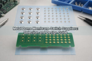
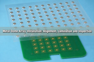
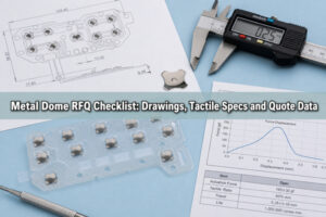
A china flex membrane circuit combines a thin printed or copper flexible circuit with overlays, spacers, adhesive and optional metal domes to create a low-profile control interface. The circuit can use screen-printed silver on PET or etched copper on polyimide FPC. Reliable construction depends on matching the conductor system, dome contact pads, vent paths, tail geometry, connector, bend zones and lamination tolerances to the operating environment.
What Is a China Flex Membrane Circuit?
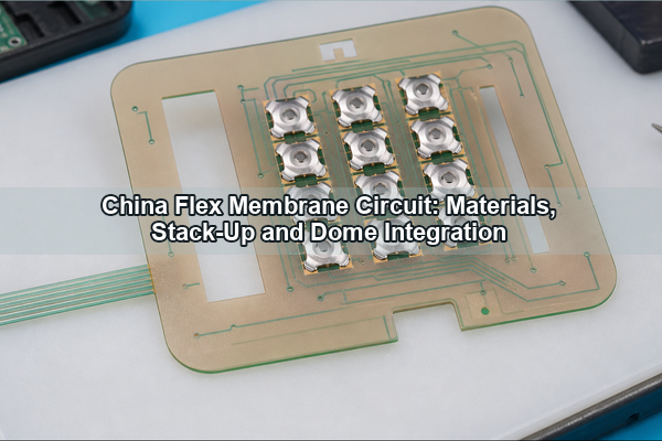
A china flex membrane circuit is a custom flexible switch circuit manufactured in China and integrated into a membrane keypad or thin control panel. It may use printed conductive inks on PET, etched copper FPC, or a hybrid construction. The functional circuit is normally laminated beneath a graphic overlay and above a rear adhesive or support layer.
The term should not be treated as a material specification. A drawing must identify the conductor type, substrate, circuit thickness, contact finish, tail, connector, dome or polydome structure, adhesive and environmental requirements. Two products sold under the same phrase can have very different current capacity, bend life, pitch capability and tactile performance.
How Does a Flexible Membrane Circuit Work?
A flexible membrane circuit routes switch signals through thin conductors and closes a normally open contact when the user presses a key. In a metal-dome construction, the dome perimeter rests on an outer contact and the dome center snaps down onto an isolated center pad. In a printed membrane switch, two circuit layers may contact through a spacer opening.
The overlay and actuator transfer force, the spacer sets the cavity, the circuit defines the electrical path, and the adhesive maintains registration. The support behind the switch must be sufficiently rigid; otherwise the panel flexes before the contact closes, increasing travel and making key feel inconsistent.
Which Circuit Constructions Are Available?
The main constructions are printed PET, copper FPC and hybrid assemblies. A screen printed flexible membrane circuit uses conductive silver or silver-carbon inks deposited on polyester. An FPC membrane switch uses etched copper on polyimide for finer routing, soldered components or demanding tail geometry. A flexible printed circuit membrane may combine a copper flex tail with laminated switch layers.
| Construction | Useful characteristics | Main controls |
|---|---|---|
| Printed PET circuit | Thin, cost-effective for simple key matrices | Ink resistance, print registration, trace width and contact wear |
| Copper FPC | Fine routing, solderable components and defined connector tails | Copper thickness, coverlay openings, bend radius and stiffener design |
| Hybrid circuit | Combines membrane layers with a copper flex or PCB interface | Transition strain, lamination datum and connector stack height |
A generic china flex pcb search may return bare flexible boards without membrane overlays or tactile contacts. The complete drawing must state whether the requirement is a bare flex circuit board, a switch circuit, or a finished keypad assembly.
PET Printed Circuit vs Copper FPC?
PET printed circuits suit low-current switch matrices with moderate routing density and limited component attachment. Copper FPC supports lower conductor resistance, finer features, plated connector fingers and soldered electronics. The choice should follow electrical load, pitch, bend requirement, operating temperature and assembly method.
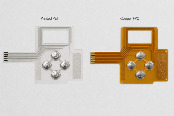
A copper flex membrane switch is preferable when the tail must mate with a ZIF connector, the circuit includes SMD components, or the routing cannot be achieved reliably with printed ink. A printed PET construction remains practical when the matrix is simple and the environmental and resistance limits are compatible with conductive ink.
How Is the Membrane Circuit Stack-Up Built?
A typical stack places the graphic overlay at the top, followed by overlay adhesive, actuator or dome carrier, spacer, circuit layer, rear adhesive and a support panel. Every layer must have a defined function; extra layers add thickness and tolerance without automatically improving reliability.
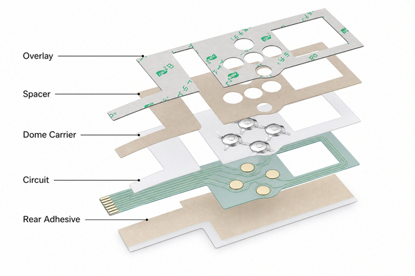
A single-layer dome array retains domes beneath one adhesive PET/Mylar carrier. A double-layer dome array can add spacing or controlled air channels. The released stack drawing should state material, thickness, adhesive zones, liner and the alignment datum used by both circuit and array.
How Are Metal Domes Integrated?
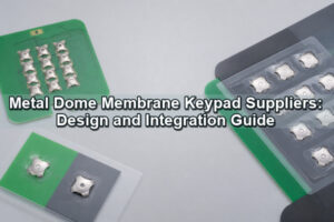
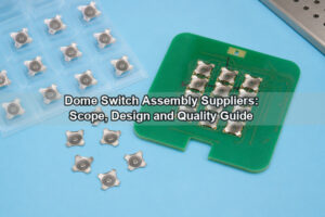
Metal domes can be placed individually, supplied as a peel-and-place sheet or laminated as a registered array. For multiple keys, a custom metal dome array improves positional consistency and keeps the carrier, adhesive cutouts, vent channels and circuit datums in one controlled design.
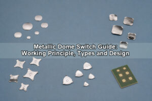
Dome diameter, shape, trip force, travel and height must match the contact pattern and actuator. Four-leg domes offer defined support points and open sectors for venting; circle domes need a continuous outer support ring. A plunger dome array can increase local height or improve force transfer when the overlay geometry cannot press the dome directly.
Which Contact Pad and Venting Rules Matter?
The center contact must remain electrically isolated from the outer contact, while every dome leg or rim must sit on one flat support plane. Coverlay or spacer edges must not fall beneath the dome support points. Traces, vias and plating steps should stay clear of the seating area unless specifically validated.
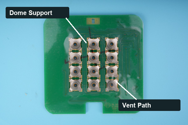
The cavity needs a route for air to leave and return during actuation. The vent may pass through open dome sectors, a die-cut spacer channel or a connected manifold. It must not terminate under adhesive or in a liquid trap. Unequal vent resistance can make identical domes feel different across the keypad.
How Do Tail, Connector and Bend Design Affect Reliability?
The tail carries signals from the key area to the main electronics and must bend away from dome footprints, stiffener edges and connector solder joints. A flex circuit board intended for repeated motion needs different copper, routing and bend radius from a tail that is folded once during installation.
A ZIF termination needs controlled finger length, plating, finished thickness, stiffener and contact-side orientation. Soldered connectors add heat and rigid mass, so strain relief is important. The enclosure model should be used to verify insertion access, bend radius and tail length at both tolerance extremes.
Which Overlay, Adhesive and Spacer Materials Should Be Specified?
Overlay material is selected for graphics, chemical exposure, flexibility and key embossing. PET is common for membrane panels; polycarbonate may be used where its printing and forming characteristics fit the environment. The adhesive must bond to the actual substrates and survive temperature, humidity, cleaning chemistry and expected shear load.
Spacer thickness sets cavity height and can affect dome preload. Adhesive cutouts must clear dome legs, contacts and vent channels. Metal-Domes publishes support for PET/Mylar dome carriers and PSA options including King Label, 3M 467 and 3M 468 on applicable array products; the selected adhesive still requires application-specific verification.
How Are Flex Membrane Circuits Manufactured?
Printed membrane circuits are produced by preparing the substrate, printing and curing conductive ink, forming contacts, die cutting or laser cutting, adding spacers and laminating the stack. Copper FPC follows imaging, etching, coverlay, finish, profile and electrical-test processes before switch layers are added.
- Release circuit artwork, stack drawing, mechanical outline and connector definition.
- Manufacture the PET circuit or copper FPC and verify continuity and resistance.
- Prepare overlay, spacer, adhesive and dome-array layers to common datums.
- Clean contacts and laminate without trapping particles or preloading domes.
- Inspect registration, vent continuity, tail geometry and finished thickness.
- Test every key electrically and verify tactile samples against the approved limits.
What Should Be Tested Before Production?
Validation should cover circuit continuity, insulation, trace resistance, contact resistance, key force, travel, return, tail fit and connector engagement. Environmental checks should match the actual product, including temperature, humidity, chemical exposure, ingress strategy and any repeated-flex requirement.
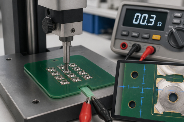
Prototype testing should use the intended backing plate and actuator because support stiffness and preload change key feel. Compare measurements by key position, not only by average, and inspect the circuit after repeated cycling for film damage, adhesive migration, cracked conductors and contact contamination.
FAQ About China Flex Membrane Circuit?
What Is a Circuit Board Membrane?
A circuit board membrane is a thin switch circuit laminated into a keypad or control panel. It can use printed conductive ink or copper FPC depending on routing and assembly requirements.
Can a Flexible Membrane Circuit Use SMD Components?
Yes, a copper FPC construction can support appropriate SMD components when pad design, assembly temperature, stiffening and handling are controlled.
Is a Screen Printed Flexible Membrane Circuit the Same as FPC?
No. Printed membrane circuits normally use conductive ink on PET, while FPC uses etched copper on polyimide. Their resistance, pitch, solderability and bend behavior differ.
Can Metal Domes Be Assembled on Flex Circuits?
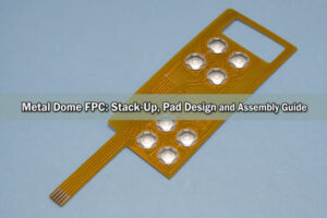
Yes. The flex needs a compatible contact pattern, flat local support, correct dome retention and a controlled vent path. The metal dome FPC design guide covers those details.
Conclusion
A china flex membrane circuit should be defined by its conductor system, stack-up, contact design, dome retention, venting, tail and connector rather than by origin alone. Printed PET suits simpler low-current matrices; copper FPC supports finer routing, soldered components and controlled connector tails. Prototype the complete mechanical stack and verify every key after lamination.
EBest Circuit(Best Technology) has manufactured metal domes and dome arrays since 2006 and can support arrays assembled with PCB or flex circuits. For drawings and application review, use the Metal Dome contact page.