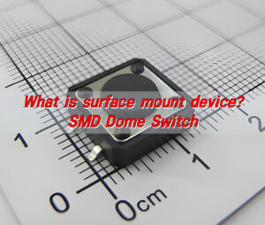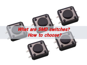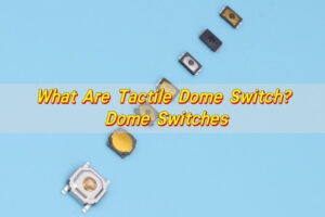

An SMT tactile switch is a momentary switch designed for direct surface mounting and reflow soldering on a PCB or FPC. The correct part must fit the board footprint and enclosure height while also meeting the required operating force, travel, electrical load, soldering profile, sealing level, packaging format and life target. Selecting only by outline size can produce weak tactile feel, poor actuator alignment, solder defects or an assembly that cannot be placed reliably.
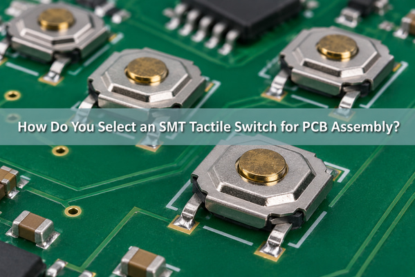
What Is an SMT Tactile Switch?
An SMT tactile switch combines a spring contact or metal dome, fixed contacts, terminals and an actuator in a package that can be soldered to surface pads. Most versions are momentary: the circuit changes state only while the actuator is pressed, then returns when the force is removed.

The tactile event and the electrical event must both be controlled. The actuator loads the internal dome, the dome snaps through, and the moving contact bridges the fixed contacts. Package construction determines whether the switch is top-actuated or side-actuated, sealed or open, low-profile or tall, and suitable for the intended reflow process.
SMT Tactile Switch vs Loose Metal Dome
A packaged SMT tactile switch is a solderable component. A loose metal dome is the spring contact itself and normally works with PCB contact pads, an adhesive carrier, a spacer and an actuator. The two routes can deliver tactile feedback, but they create different assembly responsibilities.
| Interface route | How it is assembled | Best fit | Critical check |
|---|---|---|---|
| Packaged SMT tactile switch | Pick-and-place followed by reflow soldering | Component-style PCB assembly and a defined package | Land pattern, reflow limit, actuator height and sealing |
| Custom loose metal dome | Placed over PCB or FPC contact pads and retained by the stack | Very low-profile custom key geometry | Pad design, dome support, actuator alignment and retention |
| Single-key dome array | Peel-and-place adhesive carrier positions one dome | Prototype or low-volume assembly without soldering the dome | Carrier outline, adhesive keep-out and contact-pad registration |
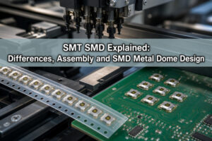
Our SMD dome switch is one packaged SMT tactile-switch route. It encloses a dome structure over its contact circuit and is supplied for direct surface mounting. A normal bare dome should not be put through reflow as though it were an SMD component.
Which SMT Tactile Switch Package Fits Your PCB?
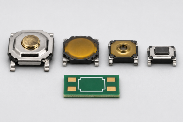
The package must satisfy the PCB footprint, overall height, actuator location, operating direction and enclosure clearance at the same time. Top-actuated parts are common when the user presses perpendicular to the PCB. Side-actuated parts suit edge controls, but they require different pad geometry and mechanical support.
Do not assume that two switches with the same nominal outline share the same land pattern. Terminal style, terminal pitch, body standoff and orientation mark can differ. Use the drawing for the exact orderable part number and place its courtyard, keep-out and height limit in the PCB library.
How Much Operating Force and Travel Do You Need?
Operating force should be chosen with the actuator, keycap, enclosure and user task. A light force can support frequent operation, while a higher force can reduce accidental activation. The installed key force can differ from the switch value because preload, off-center actuation, key geometry and housing friction add to the force path.
Travel affects both perceived movement and available tolerance. For example, our published TS5252-AADF-S4W26A drawing lists an operating force of 260 ± 40 gf and travel of 0.25 ± 0.10 mm. Those are model-specific values, not limits for every SMT tactile switch. The prototype should be measured in the final mechanical stack rather than judged only as a loose component.
Which Electrical Ratings Must Match the Circuit?
The circuit must stay within the switch rating for voltage, current and load type. Our SMD dome-switch product range lists a 50 mA, 12 VDC rating, while the exact contact resistance, insulation resistance and dielectric test conditions belong to the selected part specification.
| Parameter | What it controls | What to verify |
|---|---|---|
| Contact rating | Permitted switching voltage and current | Load type, inrush and whether the signal is logic-level |
| Contact resistance | Voltage drop and signal margin when closed | Initial limit, post-life limit and measurement current |
| Insulation resistance | Leakage while open | Test voltage, humidity condition and terminal combination |
| Dielectric strength | Short-duration insulation withstand | Applied voltage, frequency and duration |
| Bounce time | Multiple transitions after one press | Hardware or software debounce window under the actual circuit |
A maximum rating does not automatically define the minimum reliable signal load. If the circuit uses very low current, confirm the contact material and minimum applicable load for the exact series, then validate the input threshold after environmental and life testing.
How Should the PCB Footprint and Solder Pads Be Designed?
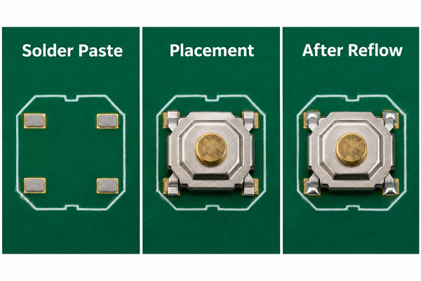
The recommended land pattern should be copied from the released product drawing, not redrawn from the body outline. Pad length must provide a controllable solder fillet without letting the part float or rotate. Solder-mask clearance, copper balance and nearby component spacing should support inspection and rework.
Place the switch so the actuator lines up with the enclosure datum, not only the PCB edge. Add a courtyard for the package body and a mechanical keep-out above the actuator. If a keycap or plunger applies side load, the package terminals should not be expected to act as the only mechanical stop.
What Stencil and Reflow Conditions Matter?
Solder-paste volume must be balanced across all terminals so the switch remains level. The stencil aperture, thickness, paste type, board finish and thermal mass should be reviewed together. Excess paste can lift or tilt the component; insufficient or uneven deposits can create weak or open joints.
The exact component drawing controls the reflow limit. The TS5252-AADF-S4W26A specification, for example, lists 150–180°C preheat for up to 120 seconds and a maximum soldering heat of 260°C for 3 seconds. We use those values only for that specified series and revision; another package may require a different profile. Confirm whether the part can be washed after soldering because the cited model specification states that washing is not allowed.
How Do Actuator Alignment and Preload Affect the Switch?
The actuator should press close to the intended center and in the specified direction. Off-center or angled loading can change the force curve, shorten travel, damage the cover or create intermittent closure. A hard keycap should include enough clearance to avoid scraping the housing.
Preload must remain below the point that partially deflects the dome or holds the contact near closure. Check the worst-case stack of PCB thickness, switch height, enclosure tolerance, keycap height and assembly compression. The mechanical stop should limit overtravel without transferring destructive load through the switch.
When Do You Need a Sealed SMT Tactile Switch?
A sealed construction is appropriate when dust, splash, flux residue or cleaning exposure could reach the contact mechanism. The specified protection level must apply to the mounted component and its stated test boundary; it does not automatically make the complete product waterproof.
Also distinguish sealed from washable. A switch may resist use-environment exposure but still prohibit post-reflow washing. If the assembly process includes aqueous or solvent cleaning, select a series whose datasheet explicitly permits that process and define the drying conditions.
How Do Tape-and-Reel Details Affect SMT Placement?
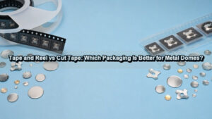
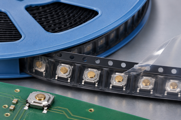
Automated placement needs more than a reel label. Confirm carrier-tape width, pocket pitch, pocket orientation, cover-tape peel behavior, reel quantity, leader and trailer length, nozzle access and the component pick surface. The machine program must use the same orientation datum shown on the drawing and packaging specification.
Our SMD dome-switch page lists 12 mm reel tape for the range. The TS5252-AADF-S4W26A drawing identifies 4,000 pieces per reel, while the website lists 5,000 pieces as the general minimum packing unit. These values describe different ordering fields and should not be treated as interchangeable. We confirm the actual reel quantity and packaging drawing for the selected part number before release.
Which Reliability Tests Should Be Included?
Reliability testing should represent the electrical load, actuation method and environment of the product. Mechanical life alone does not prove stable contact resistance at the target circuit load. The acceptance plan should identify pre-test limits, stress conditions and post-test limits.
- Operating force and travel before and after life cycling
- Contact resistance and insulation resistance under defined test conditions
- Electrical operation at the minimum and maximum intended load
- Vibration and shock with the actual PCB support
- Temperature, humidity and thermal cycling for the intended environment
- Solderability and resistance to the approved reflow profile
- Actuator alignment, overtravel and installed-key endurance
The published TS5252-AADF-S4W26A drawing lists 100,000 operating cycles. If a project needs a higher cycle count, different force or different environmental limit, that requirement must be confirmed against another qualified series rather than extrapolated from this model.
Where Are SMT Tactile Switches Used?
An SMT tactile switch is used where a compact PCB-mounted momentary input must support automated assembly. Typical applications include handheld instruments, cameras, audio controls, communication devices, compact industrial controls, medical interfaces and reset or mode buttons inside electronic products.
The application name does not select the part by itself. A camera side button may prioritize low profile and side actuation, while a service reset button may prioritize accidental-press protection. A medical or industrial interface may require sealing, controlled force and a documented life test. Translate the application into measurable electrical, mechanical and process requirements.
SMT Tactile Switch FAQs
Is an SMT tactile switch the same as an SMD tactile switch?
They normally describe the same mounting concept: a tactile switch placed as a surface-mounted device using an SMT assembly process. Always identify the exact part number because package and ratings vary.
Can a loose metal dome be reflow soldered?
A normal loose dome is not intended to be reflowed as a component. Use a purpose-built solderable SMD dome switch when direct SMT mounting is required.
Why does an SMT tactile switch have four terminals?
Many SPST packages use two electrically common terminal pairs to provide mechanical stability and convenient routing. Confirm the internal circuit diagram because pin functions are not universal.
Can the switch be cleaned after reflow?
Only when the exact series specification allows it. A sealed use rating does not by itself authorize an aqueous or solvent wash process.
What Should You Include in an SMT Tactile Switch RFQ?
To prepare our quotation, send us the PCB land pattern or Gerber data, available footprint and height, actuation direction, required operating force and travel, electrical load, target life, environment, sealing or cleaning requirement, reflow profile, tape-and-reel requirement, prototype quantity and annual volume. If an existing part must be replaced, include the complete part number, drawing and a sample when available.
At EBest Circuit(Best Technology), we can review whether an SMD dome switch, a loose custom dome or a peel-and-place dome array matches the assembly route. Send the controlled project data to sales@metal-domes.com so we can check the mechanical, electrical, soldering and packaging requirements before quotation.