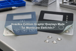
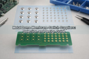
A tactile membranes prototype should prove that the complete interface works on the intended support, not merely that a printed overlay looks correct. It must connect the graphic, actuator, metal dome, circuit, adhesive, tail and enclosure into one testable assembly. At EBest Circuit(Best Technology), we support prototype and low-volume dome-array builds so customers can verify feel, fit and electrical operation before releasing a production construction.
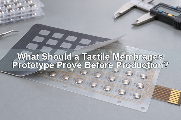
What Is a Tactile Membranes Prototype?
In this guide, the phrase tactile membranes prototype means a low-volume, working membrane interface built to evaluate physical feedback and system integration. It is not a tactile sensor membrane used in robotics, a decorative print sample, or a computer keyboard replacement membrane. The intended product is a tactile membrane switch in which pressure closes a circuit and a formed polyester dome or stainless-steel metal dome provides a noticeable snap.

A membrane switch prototype may be built at several fidelity levels. An early sample can confirm key locations and artwork, while a production-intent sample should use the proposed stack, contact geometry, dome type, adhesive and connector. The evidence from one level cannot automatically approve another. A graphic model cannot prove contact resistance, and a bare membrane tactile switch cannot prove installed key feel.
For a metal-dome version, the contact closes when the dome deflects onto the PCB, FPC or printed contact pattern. After the applied force is removed, the dome returns and opens the circuit. The prototype must show that this action remains repeatable after every layer above and below the dome is included.
Which Prototype Stage Does Your Project Need?
Choose the prototype stage according to the next decision, not according to a fixed sample quantity. A useful membrane prototype closes a defined set of questions and records which questions remain open.
| Prototype stage | What it can prove | What it cannot approve alone |
|---|---|---|
| Appearance model | Overall outline, artwork hierarchy, key grouping, window locations and basic enclosure fit | Final tactile force, electrical performance, adhesive durability or sealing |
| Functional prototype | Key operation, circuit map, connector, indicators and preliminary tactile architecture | Production repeatability or final material performance when substitutions remain |
| Production-intent sample | Proposed materials, layer stack, dome array, tooling route, installed feel and agreed inspection points | Finished-device qualification outside the quoted assembly and test scope |
| Pilot build | Work instructions, inspection flow, packaging, traceability and repeatability on an agreed lot | Future revisions or unlimited process capability |
For a prototype membrane switch, we ask which decision the sample must close: appearance, mechanical fit, tactile response, circuit operation, sealing intent or production release. If several decisions carry different risks, separate samples can be more useful than one ambiguous “final prototype.”
Which Layers Must Match Production Intent?
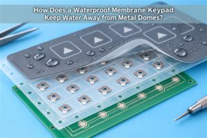
Tactile membrane switches behave as a stack. The overlay, adhesive, retainer, dome, spacer, circuit and mounting surface all influence force and travel. A production-intent prototype should therefore use the planned thicknesses, cutouts and support conditions wherever those variables affect the approval question.
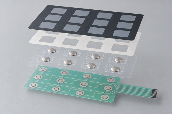
- The membrane switch graphic overlay should use the proposed film, texture, printed legends, windows and emboss geometry.
- The overlay and retainer adhesives should reproduce the planned thickness, key openings and bonding surfaces.
- The tactile element should match the intended dome family, force range, travel and center-dimple condition.
- The circuit should use the intended PCB, FPC or printed PET contact geometry and tail interface.
- The rear adhesive and mounting support should represent the actual enclosure material and flatness.
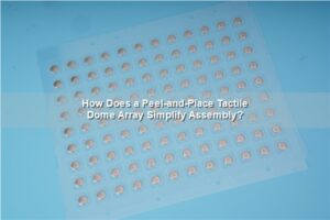
We can build a custom dome array from CAD, PDF, Gerber, PCB/CAM data or a controlled customer drawing so the dome centers and carrier outline share the same datum as the circuit. For an early, low-quantity placement check, a standard single-key dome array may provide a simpler way to test individual positions before a full carrier is released.
How Should Metal Dome Feedback Be Specified?
A membrane switch dome should be specified with measurable variables rather than words such as “soft,” “strong” or “premium.” The drawing or test plan should identify the dome shape and size, trip force, return force or click ratio when required, travel, height, tolerance and test actuator. These values remain dependent on the selected series, stack and measurement method.
The dome value is only the starting point. A tactile membrane switch can feel weaker than the bare dome if a thick overlay spreads the load, adhesive bridges an active area, the actuator is off-center or the support under the PCB flexes. It can also feel heavier if the key geometry introduces friction or excessive over-travel. We therefore compare the requested dome data with the installed force path before recommending a prototype construction.
If the project is still choosing between formed polyester and stainless-steel feedback, our polydome versus metal dome array comparison helps define the architecture before tooling. The prototype should then preserve the selected route; changing dome technology between prototype and production invalidates feel and life evidence.
How Do Overlay and Actuator Geometry Change Key Feel?
Users do not press a bare dome. They press a printed key zone, emboss, silicone key or molded keycap that transfers force through the membrane switch design. The prototype must preserve the diameter, height, alignment and stiffness of that actuator path.
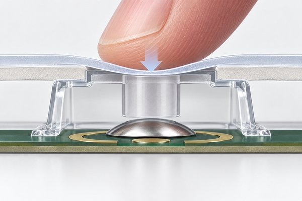
An actuator that is too small can concentrate stress on the overlay. One that is too wide can load the edge of the dome or bridge surrounding adhesive. An off-center key can tilt and produce different force readings depending on where the user presses. The enclosure should also limit over-travel so the dome is not used as the mechanical stop.
Where the keycap cannot apply a stable centered load, we can evaluate a plunger dome array. The plunger geometry becomes part of the prototype evidence, so its diameter, height and registration must be included in the approved drawing and installed test.
What Circuit, Tail and Connector Details Need Validation?
A prototype membrane switch must prove more than continuity at the key. It should confirm that the contact-pad geometry, matrix or individual wiring, tail exit, bend zones, stiffener, exposed-contact side and connector all match the device. A correct switch pattern with a reversed tail contact side can still make the assembly unusable.
- Verify every key against the released circuit map and pinout.
- Check that the center contact is electrically isolated from the outer ring or leg contacts.
- Confirm tail routing with the actual enclosure, bend radius and mating connector.
- Inspect conductor clearance around windows, screws, LEDs and cutouts.
- Measure contact resistance using the agreed fixture, force and connection method.
For a prototype membrane switch built on PCB or FPC, support stiffness also matters. The board must not bow enough to change dome travel or let the contact surfaces slide relative to the carrier. We review the circuit and mechanical support together instead of treating the switch layer as an isolated electrical drawing.
How Should Adhesive, Venting and Sealing Be Evaluated?
Adhesive holds the stack together, but it must not enter the dome cavity, cover a vent path or create a high spot under the overlay. The rear adhesive must match the real housing material, texture and cleanliness. Prototype evaluation should include edge lift, liner removal, placement tolerance and adhesive wet-out on the intended surface.
Pressing a sealed dome displaces air. Without a controlled internal vent route, trapped air can increase apparent force, slow return or make adjacent keys interact. Venting should remain inside the protected stack and should not create an uncontrolled path from the outside environment to the contacts.
For projects that need additional dome retention under flexible layers, we can review a rubber-glue metal dome array. This does not by itself prove enclosure waterproofing. The prototype still needs representative edge seals, tail exit, housing compression and application-specific ingress testing.
What Should You Test on the Assembled Prototype?
Test the tactile membranes prototype on the intended support with the planned keycap, overlay and connector. A loose sample on a bench may pass while the installed assembly feels different because the enclosure flexes, the actuator shifts or the rear adhesive changes the support condition.
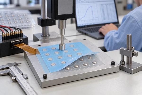
| Test area | Prototype check | Release evidence |
|---|---|---|
| Appearance | Artwork, color reference, windows, embossing and surface defects | Approved visual sample and artwork revision |
| Fit | Outline, holes, tail path, connector access and enclosure clearance | Dimension report and installed-fit approval |
| Tactile response | Trip/return behavior, travel, sound and off-center pressing | Agreed fixture, actuator, support and measured samples |
| Electrical function | Every key, matrix combination, contact resistance and connector pinout | Test record tied to circuit revision |
| Adhesion and seal intent | Bonding, edge lift, vent behavior and representative exposure | Defined substrate preparation and test conditions |
| Durability | Cycle, wear, temperature, humidity or cleaner exposure as required | Test scope, sample construction and acceptance criteria |
We can measure trip force, rebound force and life-cycle behavior for metal domes and dome arrays. The report must identify the actual sample construction and test condition. A life result for a bare dome cannot be presented as qualification of the completed customer device.
Which Failures Require Another Prototype Iteration?
A new prototype iteration is required when the proposed correction changes the evidence being approved. Examples include changing the dome series, force, actuator geometry, overlay or adhesive thickness, contact-pad layout, circuit route, tail construction, connector, sealing edge or mounting support. These changes affect fit, feel or electrical behavior and should not be closed by a note alone.
Minor cosmetic corrections may be approved by controlled artwork when they do not affect key centers, windows, embossing, tactile load or print registration. The decision should be written, not assumed. A sample that passes only after hand rework should be recorded as a diagnostic sample, not silently promoted to the production reference.
Common blockers include inconsistent key force across the panel, double actuation, slow dome return, contact chatter, a tail that cannot be installed, adhesive entering an active area and graphics that no longer align after mounting. Each blocker should be traced to a drawing, material, process or assembly condition before the next build.
How Do We Move From Prototype to Production?
Prototyping membrane switches is complete only when the approved evidence is converted into controlled production inputs. We align the overlay artwork, circuit data, dome-array file, adhesive cut file and assembly drawing to the same revision. The approved sample is then identified together with the inspection method and any remaining customer-system validation.
- Close comments against numbered drawing features and test results.
- Freeze materials, layer thicknesses, contact geometry, dome specification and connector.
- Record the approved prototype revision and physical reference sample.
- Define incoming, in-process and final inspection points for production.
- Confirm packaging, labeling and traceability for the pilot or repeat order.
EBest Circuit(Best Technology) supports prototype, low-volume and scalable production dome-array projects with a flexible no-MOQ policy, subject to material, geometry and engineering review. Our aim is to carry forward the approved force path and assembly definition, not to replace prototype evidence with a generic promise.
What Should You Send for a Prototype RFQ?
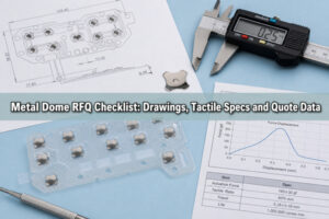
A membrane switch prototype RFQ should identify both the intended construction and the questions the sample must answer. Send the following information so we can review the build without guessing:
- A dimensioned outline or 2D drawing with key centers, mounting datums and available enclosure data.
- Vector graphic artwork with colors, windows, texture and embossing requirements.
- Circuit schematic, Gerber/PDF data, pinout, tail direction, stiffener and connector specification.
- Preferred tactile architecture, target force/travel, key-use profile and actuator geometry.
- The mounting surface, operating environment, cleaners, moisture, UV and temperature exposure.
- Prototype quantity, annual volume, required tests and the exact approval questions for this build.
Send the package to sales@metal-domes.com or use our quotation form. We will review the layer stack, force path, circuit and prototype purpose before recommending the dome-array construction. That keeps the tactile membranes prototype tied to real production decisions instead of becoming only a visual sample.