A 9 key dome button array is a compact 3×3 tactile interface in which nine stainless-steel domes provide momentary switching and a distinct snap feel. A dependable design requires more than placing nine switches in a square. Pad geometry, dome position, key pitch, vent paths, actuator alignment, adhesive construction and inspection must work as one system so that every key feels and performs consistently.
What Is a 9 Key Dome Button Array?
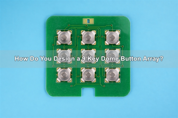
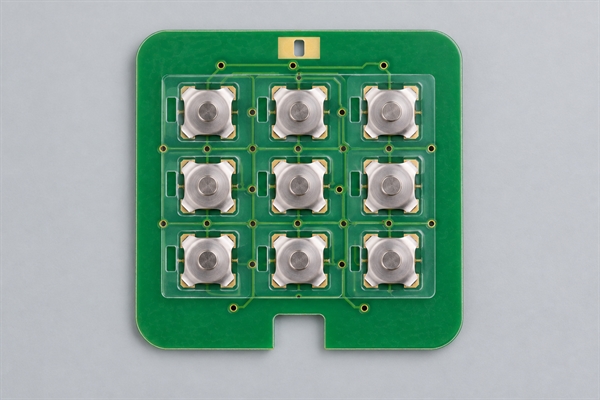
A nine-key array places three rows and three columns of tactile switch positions on one PCB, FPC or membrane circuit. At each position, the metal dome rests above a center contact and an outer contact. Pressing the key collapses the dome, connects the two contacts and produces tactile feedback. Releasing the key lets the dome recover and opens the circuit.
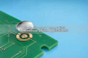
The phrase 9 button keypad describes the user-facing layout, while metal dome keypad identifies the tactile switching technology. The array may sit beneath molded keycaps, rubber keys or a graphic overlay. These terms describe related parts of one interface, but they should not be treated as identical components.
Why Use a 3×3 Dome Layout?
A 3×3 arrangement fits nine commands into a compact, familiar grid. It is useful for access controls, industrial controllers, remote controls, medical equipment and compact instruments. The layout also makes row-and-column scanning practical when the host electronics need to reduce the number of signal lines.
Mechanical symmetry does not automatically produce a consistent keypad. Edge keys may be supported differently from the center key, and a housing rib or uneven overlay can change actuation feel. The enclosure, key guides and circuit therefore need one shared datum scheme.
Should the Nine Keys Use One Dome Array or Individual Domes?
Loose domes can suit simple prototypes or low-density layouts, but placing nine separate parts increases the opportunity for rotation, offset and double placement. A carrier-based custom dome array keeps all nine domes in one registered sheet and allows the assembly to be positioned in one operation.
For a stable production process, the carrier should include usable alignment features and a defined outline. Release liner design also matters: operators or automated equipment need to expose and place the adhesive without stretching the film or disturbing the domes.
How Should the PCB Contact Pattern Be Designed?
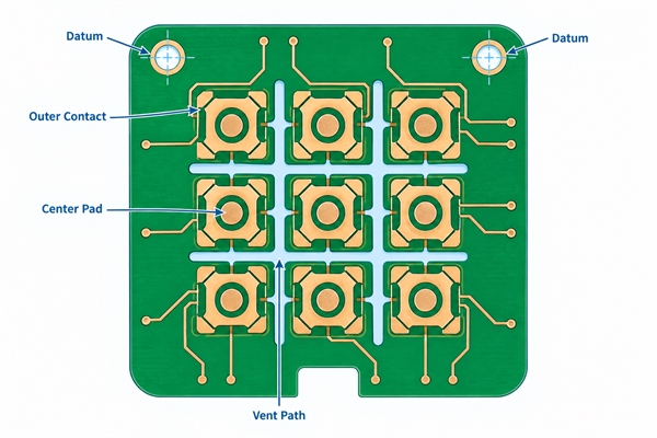
Each switch position needs a center pad and a separate outer contact. The dome must bridge those contacts only when it collapses. The outer contact should support the dome evenly, while solder mask, copper features and nearby components must stay clear of the dome footprint.
The pad finish should be flat, conductive and compatible with the environment. Debris, oxidation, uneven plating or solder residue can increase contact resistance. The selected dome drawing should control the land pattern; a generic footprint should not be reused without checking dome diameter, feet, travel and target force.
How Do Key Pitch and Alignment Affect All Nine Buttons?
Key pitch is the center-to-center distance between adjacent buttons. It must provide enough room for the dome footprint, adhesive seal, vent path and actuator guide. When the pitch is too small, neighboring features can restrict air movement or weaken the carrier. When it is too large, the keypad wastes panel area and may no longer match the enclosure.
Use the same origin, X-Y pitch and orientation in the PCB, carrier, overlay and housing files. Two or more well-spaced datum features are preferable to aligning from a cosmetic edge. A tolerance stack should include PCB fabrication, printed artwork, carrier cutting, adhesive placement and molded key location.
Which Dome Shape, Force and Travel Should You Specify?
Four-leg domes provide stable support and are well suited to many keypad layouts. A four-leg metal dome should be selected by actual diameter, force, travel and click ratio rather than by appearance alone. All nine keys normally use the same specification when the interface requires a uniform feel, although mixed-force arrays are possible when one function needs deliberate differentiation.
| Design input | What to define | Risk if it is unclear |
|---|---|---|
| Dome geometry | Series, diameter and orientation | Pad mismatch or unstable support |
| Operating force | Target force and acceptable tolerance | Uneven feel across nine keys |
| Travel and click ratio | Required tactile response | Weak snap or excessive key motion |
| Key pitch | X and Y center spacing | Carrier, vent or housing interference |
| Environment | Temperature, humidity and contamination exposure | Adhesive or contact reliability problems |
As a published capability range, our dome arrays can be engineered for approximately 100-400 gf force and 0.13-0.30 mm travel, with the final specification subject to dome size, structure and application review. These ranges are design boundaries for discussion, not a promise that every combination is available.
How Should Venting Work Across a 3×3 Keypad?
Air below a dome must move when the dome collapses and recovers. A trapped pocket can slow return, change force or create a muted feel. Each key therefore needs a controlled vent route that remains open after the carrier and overlay are laminated.
Individual vent channels can lead from each position to a safe open area, or several keys can share a manifold when the layout and contamination requirements permit it. The design should prevent adhesive squeeze-out, housing ribs or printed ink from blocking the route. A vent should not open directly toward dust, liquid or cleaning fluid without an environmental sealing strategy.
When Does a Plunger or Keycap Improve Actuation?
A molded key or rubber key should press near the dome center. Off-center loading can increase wear, distort the click and shift the dome. When the key cannot reach the dome consistently, a plunger dome array can provide a defined contact point and added height.
Our published plunger options cover approximately 0.8-3.2 mm diameter and 0.1-0.40 mm added plunger height, subject to engineering evaluation. The actuator tip should be smooth, centered and sized to transfer force without denting the dome or rubbing adjacent film.
How Do Overlay, Spacer and Adhesive Layers Affect Feel?
The overlay presents the key legend and protects the switch area. The spacer controls clearance around the dome, while the pressure-sensitive adhesive secures the array to the circuit. These layers also influence force transmission, acoustic response and sealing.
Adhesive must be compatible with the PCB surface, expected temperature and assembly process. Its die-cut openings should not touch the active dome area. The liner should release cleanly, and the carrier should remain flat during placement. A single-layer dome array construction can simplify positioning when the application does not require a more complex overlay stack.
What Electrical and Mechanical Checks Are Needed?
Verification should combine electrical continuity with force-displacement measurements. Test every key, not only one representative position. The nine results reveal whether the center, edge and corner keys behave differently after lamination or enclosure assembly.
- Confirm open-circuit isolation before actuation and stable contact closure during actuation.
- Measure operating force, return behavior and travel at each of the nine positions.
- Check repeatability after environmental conditioning and life cycling when required.
- Test the finished keycap or overlay stack because the actuator can change the measured feel.

Which Defects Should Inspection Catch?
Visual inspection should identify missing, doubled, rotated or offset domes; wrinkles in the carrier; contamination on contacts; blocked vent paths; damaged liners; and adhesive intrusion. Dimensional inspection should confirm the array outline, datum position and key pitch against the approved drawing.
A good appearance is not enough. A dome can look centered but still have an inconsistent force curve or intermittent contact. For that reason, the acceptance plan should connect visible defects with electrical and tactile tests.
How Can You Prevent Uneven Key Feel?
Start with one controlled dome specification and one pad geometry for all equivalent keys. Keep actuator tips centered, maintain equal support beneath the circuit and avoid local adhesive thickness changes. During pilot assembly, compare corner, edge and center keys after the complete housing is fastened.
If a function intentionally needs a different force, document it as a separate key class instead of accepting an unexplained variation. The drawing, bill of materials and inspection report should clearly identify that exception.
What Should You Send for a Custom 9-Key Project?
Send the PCB or FPC layout, array outline, X-Y key coordinates, dome series or target force, expected travel, actuator details, overlay stack, venting requirements and environmental conditions. CAD, PDF, Gerber, PCB or CAM files help us verify the same geometry across the circuit and carrier.
At EBest Circuit(Best Technology), we review the nine switch positions as a complete tactile system rather than nine isolated parts. To discuss a 9 key dome button array, send your drawing and test requirements to sales@metal-domes.com. We can support prototypes, small quantities and scalable production after the design and acceptance criteria are confirmed.