
Metal dome switches for automotive buttons turn a keycap press into a short, repeatable electrical contact with a clear snap response. A dependable design requires more than selecting a dome by diameter and force. The keycap, actuator, dome, adhesive carrier, PCB or FPC contact pattern, vent path, backlight and enclosure must work as one mechanical stack. This guide shows how to convert the desired button feel and vehicle environment into a manufacturable dome specification.
What Are Metal Dome Switches for Automotive Buttons?
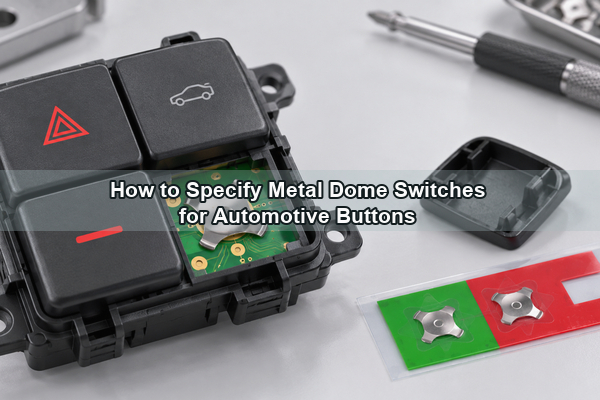
A metal dome switch is a shallow formed stainless-steel contact placed over a PCB or flexible-circuit pad. Its perimeter rests on the outer contact. When the driver presses the button, the dome snaps through and touches the center contact, closing the circuit. After the load is removed, the dome returns and opens the circuit.
This metal dome structure combines the spring and moving contact in one thin component. It is used where physical buttons in cars need a positive tactile event without the height of a conventional packaged switch. A tactile metal dome switch can support steering-wheel controls, HVAC panels, center-console keys, door controls and other compact interfaces, but the finished result depends on the complete button assembly rather than the dome alone.
The terms metal snap dome, metal dome button, dome button switch and tactile dome switch often describe the same snap-through principle. They do not automatically define the dome shape, force, plating, carrier construction or environmental qualification. Those details must be stated on the drawing and validated in the assembled key.
Where Does the Dome Fit in the Automotive Button Stack?
The visible automotive button is only the top of the load path. A typical stack includes a molded keycap, a centered plunger or elastomer feature, a spacer or carrier layer, the metal dome, a PCB or FPC contact pattern and a rigid support. Optional sealing, graphic and light-guide layers add further interfaces.
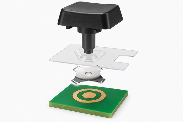
Each layer changes the finished feel. A flexible PCB can absorb travel. A stiff overlay can add preload. A tall or off-center plunger can tilt the dome. A blocked cavity can slow return. The mechanical datum, actuator centerline and circuit support therefore need to be defined before the dome force is frozen.
How Do You Convert Button Feel Into Measurable Dome Targets?
Words such as crisp, soft or premium are useful design goals, but they are not acceptance criteria. The specification should translate them into measurable variables for both the loose dome and the finished automotive button.
| Variable | What it controls | Why assembly-level verification matters |
|---|---|---|
| Trip force | Load at snap-through | Keycap leverage and overlay stiffness can raise or lower the felt force |
| Return force | Ability to reset the key | Preload, adhesive intrusion and friction can delay return |
| Travel | Movement before and through contact | Stack clearance and actuator height determine usable travel |
| Tactile ratio | Contrast between peak and post-snap force | The surrounding structure can damp the click even when the loose dome passes |
| Force tolerance | Key-to-key and lot-to-lot consistency | Multi-button panels make variation easier for users to notice |
Measure with the intended actuator diameter, loading point and support condition. If several keys must feel matched, define the acceptable spread within one panel as well as the component tolerance. This prevents a dome that meets a loose-part drawing from producing an inconsistent finished interface.
Which Dome Shape and Delivery Format Fit the Design?
Shape should follow the pad geometry, available footprint, vent route and actuator. Four-leg metal domes provide defined support points and open spaces between the legs, which can help a designer route air and fit surrounding features. Circle, triangle and oblong domes suit different footprints, but their contact patterns are not interchangeable.
Delivery format is a separate decision. Loose snap dome buttons leave placement and retention to the assembler. A custom metal dome array holds multiple domes at controlled coordinates under a die-cut carrier, reducing individual handling and making a multi-key panel easier to register in one operation.
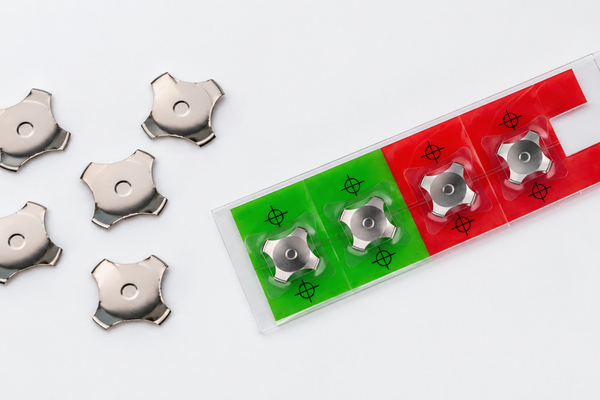
A dome switch vs membrane decision should not be treated as a choice between tactile and non-tactile operation. A membrane dome switch can use a metal dome beneath a membrane or carrier layer. The practical question is who controls dome registration, adhesive, venting and final assembly.
How Should the Actuator and Keycap Transfer Force?
The actuator should contact the dome near its center and remain centered throughout the key travel. Its end diameter must be large enough to load the crown predictably but small enough to avoid the legs and surrounding adhesive. The key guide should limit side load and rocking, especially for large or asymmetrical automotive buttons.
For a tall stack or a defined air gap, a plunger dome array can integrate the load-transfer feature with the registered tactile layer. Plunger height, diameter, material hardness and tolerance still need to be matched to the enclosure and dome. A plunger is not a cure for an unstable keycap or a flexing circuit support.
- Align the actuator centerline with the dome crown and PCB pad center.
- Control preload so the dome is not partially collapsed at rest.
- Provide hard stops when the key mechanism could over-travel the dome.
- Evaluate off-axis presses at the edges and corners of the visible keycap.
How Should PCB or FPC Contacts, Venting and Placement Be Designed?
The circuit normally uses an outer contact region that supports the dome and an isolated center contact that is reached at snap-through. Pad dimensions, finish, solder-mask clearance and support flatness must match the selected dome. Exposed vias, debris, uneven plating or adhesive squeeze-out can interfere with seating and contact stability.
Air must leave and return to the dome cavity during every press. A vent can be routed through a spacer channel, between four-leg dome feet or through another controlled path. It should not terminate in a sealed pocket or create an uncontrolled route for moisture. Our PCB contact pad design guide explains pad, clearance and venting details that should be reviewed with the dome drawing.
For an FPC, the backing plate and attachment method are part of the electrical contact system. Local flex changes dome support and force response. Registration marks, locating holes and the peel-and-place method should be defined so the array is applied without stretching or trapping contamination.
What Must Be Considered for Backlighting, Sealing and Vehicle Environments?
Backlighting and sealing add constraints around the same small cavity. An LGF dome array can distribute light across a keypad while retaining tactile domes, but LED position, light-entry features, opaque areas and button legends must be designed together. A light guide should not create preload or obstruct dome travel.
Sealing depends on the complete interface, not on calling the dome itself waterproof. Adhesive selection, perimeter geometry, vent strategy, connector exit, housing joints and substrate surface all influence the result. Temperature, humidity, cleaning chemistry, vibration and contamination requirements should come from the customer’s actual installation and qualification plan.
EBest Circuit(Best Technology) can manufacture loose metal domes and custom dome arrays for PCB or FPC-based button assemblies. We review the dome geometry, carrier construction, adhesive, actuator relationship and circuit interface against the supplied drawings. We do not treat a standard dome as automatically qualified for every automotive environment; required tests and acceptance limits must be agreed for the project.
How Should Automotive Button Prototypes Be Evaluated?
Prototype evaluation should separate component behavior from assembly behavior. First confirm the dome outline, plating, force curve and surface condition. Then apply the intended carrier to the actual PCB or FPC and test through the production-representative keycap and actuator.

- Record trip force, return force, travel and tactile ratio for every key position.
- Check center, edge and corner presses for actuator tilt or incomplete switching.
- Confirm contact resistance and signal behavior under the specified electrical load.
- Inspect dome position, carrier lift, adhesive intrusion and vent continuity.
- Run environmental and life tests under customer-defined conditions, then repeat the tactile and electrical measurements.
The image above is an engineering illustration, not a customer case or a photograph of a released automotive production line. The real fixture, sampling plan and limits must match the approved drawing and validation requirements.
How Do We Control Production Consistency and Engineering Changes?
Automotive switches and buttons are judged as an interface, so lot control must extend beyond a single nominal force value. We can review incoming material, dome forming, plating condition, carrier registration, adhesive lamination and finished-array inspection against the released specification. The control plan should identify which characteristics are measured per lot and which are verified during periodic or qualification testing.
Changes to dome material, plating, tooling, adhesive, carrier thickness, release liner, die cutting or packaging can alter fit or feel. Revision control should link the dome drawing, array artwork, PCB/FPC data and key-stack drawing. When a change affects the load path or contact interface, the assembled button should be re-evaluated rather than approved from a component certificate alone.
What Information Should Be Defined Before Sampling?
A complete project brief lets us check manufacturability before samples are built. Send the intended application, annual and prototype quantities, dome coordinates, PCB or FPC contact drawing, key-stack section and required qualification conditions. If the button feel is based on an existing sample, provide both the target feel description and measurable force-travel data when available.
| Project input | Minimum information | Decision supported |
|---|---|---|
| Dome | Shape, diameter, force target, travel, plating and tolerance | Series and forming feasibility |
| Array | X-Y coordinates, outline, holes, carrier, adhesive and vent paths | Registration and lamination method |
| Actuator | Tip diameter, height, tolerance, key travel and hard stop | Load transfer and preload risk |
| Circuit | Pad artwork, finish, solder mask, substrate and backing support | Contact stability and placement |
| Environment | Temperature, humidity, contamination, vibration and test plan | Material choice and validation scope |
| Production | Supply format, packaging, inspection, traceability and change control | Line integration and acceptance plan |
Use this metal dome switches for automotive buttons specification guide as the discussion checklist, then send drawings and target quantities to our engineering team or email sales@metal-domes.com. We will review the dome, carrier, actuator and circuit as one tactile system before recommending a sample route.