metal dome selection guide decisions should begin with the installed switch, not an isolated dome. The PCB contacts, actuator, overlay, spacer, vent path and assembly process all change the force response. A dome that passes a loose-part test can still feel weak, bind or make intermittent contact after installation.
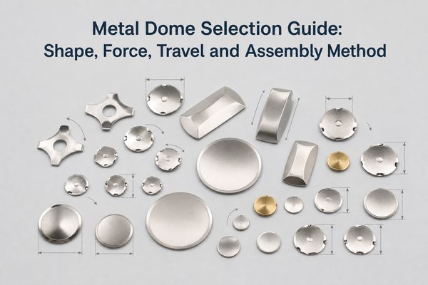
This guide provides a practical sequence for selecting shape, size, force, travel, plating and supply format. The aim is to qualify the simplest standard part that meets the complete switch requirement, then move to a custom design only when a measured constraint makes it necessary.

What Should You Check Before Selecting a Metal Dome?
Define the switch stack and operating conditions before comparing catalog part numbers. At minimum, establish:
- PCB contact geometry, surface finish and available keep-out area;
- actuator tip diameter, alignment tolerance and maximum stroke;
- overlay and spacer materials, thickness tolerances and expected preload;
- target trip force, return force, travel and tactile contrast;
- electrical signal level, contact-resistance limit and environmental exposure;
- expected life, test method and assembly volume;
- whether the factory will place loose domes, a pre-aligned array or tape-and-reel parts.
These inputs prevent a common mismatch: choosing a dome by diameter and nominal force, then discovering that the enclosure cannot accommodate its height or that the actuator loads it off-center.
Which Metal Dome Shape Fits the PCB Layout?
Shape is primarily a mechanical and routing choice. Support points, contact geometry and actuator position differ, so two shapes with the same nominal force are not automatically interchangeable.
| Shape | Useful When | Main Boundary | Practical Check |
|---|---|---|---|
| Round | The actuator is centered and a low-profile, symmetrical key is required | The PCB needs a suitable center contact and outer support/contact geometry | Confirm pad clearance around the full circumference |
| Four-leg | Traces must pass between defined support points or the dome needs stable orientation | Leg direction must match the footprint and placement process | Lock rotation in the drawing and assembly fixture |
| Triangle | The layout is compact or a high-force option is required | Orientation and actuator centering are more sensitive | Check the support points and intended PCB holes or locating features |
| Oblong | The key or enclosure is long and narrow | Off-axis loading can create uneven collapse | Test both intended actuation locations and edge loads |
| Custom | Standard outlines conflict with components, contacts or enclosure geometry | Tooling, sampling and replacement risk increase | Document the functional reason for every custom feature |
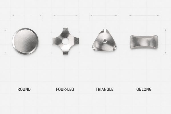
EBest Circuit(Best Technology) publishes standard options for circle metal domes, four-leg metal domes, triangle metal domes and oblong metal domes. Start with the shape that fits the PCB and actuator, then select force and travel within that shape family.
How Should Metal Dome Size Be Selected?
The dome must fit the usable PCB area with clearance for placement variation, adhesive, nearby components and the full collapse envelope. Do not use enclosure opening size as the dome diameter without checking the actuator and contact footprint.
Larger diameter does not automatically mean higher force. Force depends on geometry, material thickness, formed height and heat treatment. As published series ranges, circle domes cover 3-20 mm with typical trip forces of 100-600 gf, while four-leg domes cover 5-20 mm with typical trip forces of 125-500 gf. Not every diameter is available at every force, so confirm the exact size-force combination against a released drawing.
Use these checks when narrowing the size:
- Keep the actuator tip within the dome's effective center region at worst-case lateral tolerance.
- Leave clearance for the dome to collapse without touching solder mask steps, component bodies or enclosure ribs.
- Verify that the PCB contact pattern scales with the selected dome rather than stretching a generic footprint.
- Include free height and installed stack height in the enclosure tolerance analysis.
- For elongated keys, check whether an oblong part or a guided actuator gives more consistent loading than simply increasing a round dome diameter.
How Do Trip Force, Return Force, Travel and Click Ratio Work Together?
Trip force is the peak load immediately before snap-through. Return force is measured as the dome recovers. Travel is the displacement through the defined actuation event. Click ratio expresses the force drop that creates tactile contrast:
Click ratio = (trip force – return force) / trip force x 100%
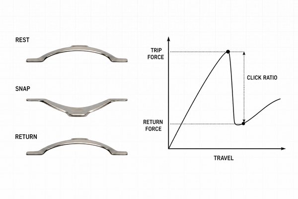
| Parameter | What It Controls | What Must Be Defined |
|---|---|---|
| Trip force | Peak effort required to actuate | Actuator geometry, test speed and whether the reading is loose-part or installed |
| Return force | Recovery margin after release | Minimum acceptable return under overlay preload and tolerance extremes |
| Travel | Displacement available for snap and contact | Datum, maximum actuator stroke and enclosure stop |
| Click ratio | Relative force drop and tactile contrast | Calculation method and acceptable range, not only a nominal target |
A higher click ratio can produce a more distinct snap, but it cannot compensate for poor alignment, excessive preload or trapped air. Two domes with the same trip force can feel different because their return force, travel and curve shape differ. Approve the complete force-displacement curve and keep the measurement fixture consistent between prototype and production.
Which Material and Plating Option Is Appropriate?
Stainless spring steel is the normal base material because it provides elastic recovery and fatigue resistance. Plating should be selected as part of the electrical contact system, together with the PCB finish, signal level, expected contamination and environment.
| Surface Option | Selection Reason | Boundary to Validate |
|---|---|---|
| Bare stainless steel | General switching in a controlled environment | Contact resistance, cleanliness and long-term surface behavior |
| Nickel plating | Added surface protection or compatibility with a defined contact system | Mating finish and life-test stability |
| Silver plating | Low-resistance contact for selected applications | Tarnish exposure and storage environment |
| Gold plating | Stable low-level contact in demanding or corrosive conditions | Added cost must be justified by electrical or environmental requirements |
Do not specify plating only because it appears more durable. Test the selected dome surface against the production PCB finish after the intended cleaning, lamination and environmental process. A material or plating change after tactile approval can alter the force curve or contact performance and requires revalidation.
Should You Use Loose Domes, a Dome Array or Tape-and-Reel?
Supply format is an assembly decision. It should match placement equipment, key count, volume and allowable positioning error.
| Supply Format | Best Fit | Main Advantage | Main Control Point |
|---|---|---|---|
| Loose dome | Prototype, repair or low-volume manual assembly | Flexible and simple for a few positions | Orientation, centering, contamination and double-doming |
| Dome array | Multiple keys or a membrane-switch stack | Domes arrive aligned on an adhesive carrier | Carrier dimensions, adhesive windows, vents and stack thickness |
| Tape-and-reel | Automated placement at repeat volume | Compatible with controlled feeder and placement processes | Pocket orientation, pickup method and placement recipe |
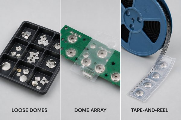
A custom dome array can combine different dome sizes, shapes and forces on one carrier while preserving key locations. It is useful when manual placement would add too much alignment variation. Tape-and-reel is preferable when the line already supports automated dome placement and the part geometry is compatible with pickup and feeder controls.
How Do PCB Pads, Actuators and Venting Affect the Selection?
In a typical normally open metal dome switch, the dome rests on an outer contact. When pressed, its center reaches the isolated center pad and closes the circuit. The footprint must match the selected dome drawing, including support points, leg orientation and collapse clearance.
Control the surrounding interface as carefully as the dome:
- Keep vias, solder mask steps, silkscreen and raised copper away from the movement area unless the approved footprint allows them.
- Use a flat, clean contact finish and define acceptable residue after assembly.
- Center the actuator and control its tip diameter, end shape and maximum stroke.
- Avoid excessive overlay or enclosure preload that reduces available return force.
- Provide a vent path through the spacer, adhesive or PCB so displaced air can move freely.
- Check PCB bow and support conditions, especially across multi-key metal dome keyboard layouts.
Blocked vents can cushion collapse, slow return and create key-to-key variation. An actuator that is too narrow or offset can dent the dome, load one leg first or shorten life. These problems cannot be corrected by choosing a higher nominal force.
When Is a Standard Metal Dome Better Than a Custom Dome?
A standard dome is the better choice when it meets the installed footprint, force curve, travel, surface and life requirements. It reduces tooling cost, sample iterations, replacement risk and dependence on a unique geometry.
Use a custom metal dome only when a documented requirement cannot be met by an available series. Valid reasons include a non-standard outline, unusual leg orientation, special center hole, constrained height, defined force-return curve or contact geometry that cannot change.
Before opening custom tooling, compare at least two standard candidates in the actual switch stack. If a standard part works after a reasonable actuator or spacer adjustment, that solution is normally easier to validate and sustain. Customization should solve a functional constraint, not simply make the drawing unique.
How Should Candidate Domes Be Tested in the Final Stack?
Loose-part force measurement is useful for incoming control, but product release requires installed testing. Build prototypes with production-intent PCB finish, adhesive, spacer, overlay, actuator and enclosure support.
Test at nominal and tolerance-limit conditions:
- Measure trip force, return force, travel and contact closure with the intended actuator.
- Repeat measurements across multiple keys and locations to identify PCB bow or stack variation.
- Check operation at minimum and maximum spacer, overlay and enclosure dimensions.
- Run life cycling at the real actuator alignment and stroke; do not overtravel the dome with the test fixture.
- Recheck force response, contact resistance and visible deformation after cycling.
- Add temperature, humidity or contamination tests when the operating environment requires them.
EBest Circuit(Best Technology) can measure trip force, rebound force and life-cycle behavior, but approval criteria should still describe the customer's installed stack and test fixture. A supplier measurement and a finished-product measurement are comparable only when their methods and datums are defined.
What Metal Dome Selection Mistakes Should You Avoid?
- Choosing by diameter and trip force alone.
- Treating trip force as a complete description of tactile feel.
- Reusing one PCB footprint for round, four-leg, triangle and oblong parts.
- Allowing the actuator to load an edge or leg before the dome center.
- Blocking the vent path with adhesive, printing or enclosure features.
- Adding gold plating without an electrical or environmental requirement.
- Selecting loose domes for a high-key-count assembly without controlling placement error.
- Opening custom tooling before evaluating standard candidates in the final stack.
- Approving loose-dome samples without production-intent assembly and tolerance testing.
- Changing dome material, plating, height or fixture method after approval without revalidation.
FAQ
What is the difference between a metal dome and a snap dome?
In tactile-switch discussions, metal dome, snap dome and tactile dome often describe the same formed spring contact. The released drawing and performance parameters matter more than the naming convention.
Is a higher trip force always more durable?
No. Durability depends on dome geometry, material, forming process, actuator alignment, overtravel, PCB support and environment. Higher force can reduce accidental activation, but it is not a direct life rating.
What metal dome shape gives the best tactile feel?
There is no universal best shape. Four-leg domes can provide strong tactile definition and routing space, round domes suit low-profile centered keys, triangle domes fit selected compact or high-force layouts, and oblong domes fit long narrow areas. Installed geometry determines the result.
How much actuation force should a tactile dome switch use?
Choose force from user input, actuator leverage, accidental-press risk and return margin. Handheld keys usually need a different target from guarded industrial controls. Validate the range with representative users and the final actuator, rather than relying on a catalog nominal value alone.
Does a metal dome need a dimple?
Not always. A dimple can help define the center contact or manage overtravel in some structures, but it also changes stress distribution. Select it only when the PCB contact and life-test results support the feature.
Can different dome forces be used in one metal dome array?
Yes. A custom array can combine different released dome part numbers, provided their locations, orientations, carrier construction and actuator stack are controlled.
When should tape-and-reel be selected?
Use tape-and-reel when production volume and equipment justify automated placement, and when the dome shape can be reliably presented, picked and oriented. Confirm reel direction, pocket design and pickup method before line qualification.
Why does a dome feel different after assembly?
Overlay stiffness, spacer thickness, preload, actuator offset, PCB bow, adhesive intrusion and blocked vents all change the installed force curve. This is why final-stack testing is required.
What information should be fixed before approving a dome?
Freeze the dome drawing, PCB footprint, actuator geometry, stack dimensions, surface finish, force-displacement limits, test method, life requirement and supply format under matching revision control.
Conclusion
A reliable selection starts with the complete switch stack. Match shape and size to the PCB and actuator, define trip force together with return force and travel, choose plating as part of the contact system, and select the supply format around the actual assembly process. Use a standard dome where it meets the installed requirement and reserve customization for a documented functional constraint.
Use this metal dome selection guide with the released PCB and mechanical stack. For engineering feedback on candidate parts or prototype test conditions, contact EBest Circuit(Best Technology) at sales@metal-domes.com.