
Metal dome contact contamination can leave a switch clicking normally while the electrical input misses presses or responds only when pushed harder. A particle, residue or adhesive transfer may interrupt the path between the dome and PCB contact pads. Diagnose the electrical path before replacing the dome: compare the failed key with a working key under the same input conditions, inspect the contact area, then retest after a controlled correction.
What Is Metal Dome Contact Contamination?
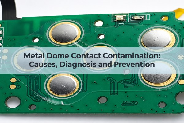
It is unwanted material on a surface that must carry current when the dome is pressed. The affected surface may be the dome’s center contact, its perimeter support, the PCB center pad or the surrounding pad. A visible fiber can keep a tiny contact area apart; a thin residue can create a less obvious, variable resistance. A crisp tactile snap proves that the spring moved, not that both electrical interfaces closed.
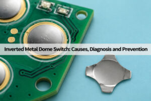
The switch geometry matters. A round C-series metal dome and a four-leg F-series metal dome use different support and PCB-pad layouts. Identify the actual current path from the drawing before deciding which apparently clean area to inspect. A mark outside that path may be cosmetic; a barely visible film on a contact point may be functional.
Where Does Contamination Under a Metal Dome Collect?
Check the center pad, the surrounding contact or support region, the underside of the dome and the boundary of the adhesive carrier. Contamination under a metal dome may be trapped when the dome or array is placed. It can also enter later through an unprotected opening or migrate from an unsuitable adhesive or cleaning residue. The location of the material relative to the real electrical path is more important than its apparent size.
Look at neighboring keys and unused boards from the same lot. Material repeated at the same edge points toward a process or carrier issue; a single isolated fiber is more consistent with a local handling event. These are diagnostic leads, not proof. Record the key position and material appearance before wiping anything away, or the most useful evidence may disappear.
Can Debris on PCB Contact Pads Cause an Intermittent Switch?
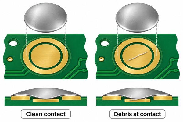
Yes. Debris on PCB contact pads can obstruct a contact point or shift the dome enough to make closure force-dependent. A switch may pass one manual press and fail the next. The same symptom can come from a damaged dome, misalignment, worn plating or a faulty trace, so debris should not be declared the cause merely because it is visible nearby.
Inspect both sides of the interface under suitable magnification and lighting, then compare the failed key with an adjacent passing key of the same design. If the contact surface is scratched, pitted or corroded, simply removing a loose particle may not restore it. Conversely, a clean pad does not rule out material on the underside of the dome.
Why Can a Dome Click While Its Contact Is Intermittent?
The mechanical snap and electrical closure are related but separate events. The dome can invert and return while an insulating particle prevents dependable contact at the center pad. In a low-current input, an unstable interface may produce a voltage the controller does not consistently interpret as a valid press. Pressing harder can temporarily force a connection without identifying the underlying defect.
Also check the actuator and carrier. Off-center loading, a shifted array or a blocked vent path can change how the dome reaches the pad. If the click itself has changed, compare force and travel as well as continuity; a purely electrical explanation may miss a mechanical fault. Avoid repeatedly over-pressing a suspect key because that can alter the part before inspection.
How Do You Isolate the Faulty Contact Path?
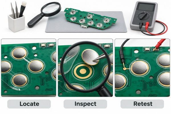
First reproduce the failure in the assembled unit and note which key, orientation, actuation force and environment make it occur. Next compare its pad-to-pad electrical response with a known-good key under the same test circuit. With power removed, inspect the dome position, film, pad finish and traces. Only after recording the as-found state should you lift a removable part under an approved rework procedure.
Use the change in outcome to narrow the cause: if replacing the dome alone clears the fault, inspect the original dome and its mounting; if a verified clean dome still fails at one PCB position, inspect that pad and trace. Do not interchange parts across production units without lot traceability. A swap test is a diagnostic method, not permission to release a repaired assembly without the required validation.
If removing the actuator changes the failure, check whether its load point was pushing the dome off-axis. If the result changes only after lifting the adhesive film, document that disturbance: the action may have dislodged debris, but it may also have changed alignment or venting. Compare the as-found photographs before calling the particle the root cause.
How Should You Test an Intermittent Dome Contact?
Test at the intended input voltage and current, with the same actuation method and timing used for the comparison key. A continuity beeper alone is weak evidence: its test current, threshold and audible response may differ from the actual low-current input. Capture repeated presses and the closed-state voltage or resistance, and note whether the fault follows a particular force, location or time after release.
For example, consider a hypothetical 3.3 V input with a 10 kOhm pull-up. At the same controlled actuation, one key repeatedly pulls the node to 0.02 V while the suspect key sometimes stays at 1.8 V. Those are observations under a stated circuit condition, not our production measurements or acceptance limits. The difference supports investigating the suspect current path; it does not by itself prove contamination or define whether 1.8 V is a logic high or low for the actual controller. Check that controller’s thresholds, then inspect and retest the interface.
After any corrective action, repeat the test at the original failing condition and at the conditions required by the product specification. Log the number of presses, voltage or resistance range, force method and pass criterion from the approved drawing or test plan. Without a pre-correction baseline and a defined criterion, a single successful click is not a verified repair.
| Observation | Check next | Decision supported |
|---|---|---|
| Click is normal; node voltage varies between presses | Compare pad-to-pad response and inspect both contact faces | Investigate electrical interface before changing actuator |
| Failure stays at the same PCB position with a verified substitute dome | Inspect pad finish, trace and local contamination | PCB-side cause is more likely; not yet proven |
| Failure follows the original dome to a verified position | Inspect underside, geometry and plating | Dome-side cause is more likely; confirm by repeat test |
| Every key changes under the same test condition | Check supply, input circuit and test setup | Do not attribute a system-wide symptom to one particle |
When Is Cleaning Appropriate, and When Is Replacement Better?
Cleaning can be considered when the material is identifiable, loose and removable under an approved method that does not damage the specified finish, adhesive or film. Isolate the unit, follow the board and switch material instructions, and use a compatible cleaning agent only if the assembly specification permits it. Never flood an adhesive dome array or scrape a contact pad merely to make one bench test pass.
Replace or escalate when a dome is bent, its plating or pad finish is damaged, adhesive has migrated under the contact, the carrier no longer locates the dome, or contamination returns after cleaning. A fixed metal dome array may not be serviceable as a loose part; lifting it can change adhesive placement or venting. For that construction, decide between approved array rework and full replacement from the documented process, then retest the entire affected key group.
Before selecting a cleaning agent, verify compatibility with the PCB finish, dome plating, carrier film and pressure-sensitive adhesive. A solvent that leaves the pad bright can still weaken the film bond or carry residue into a vent. Where compatibility or access is unknown, quarantine and investigate instead of improvising a bench cleaning procedure.
How Can Assembly Prevent Contact Contamination?
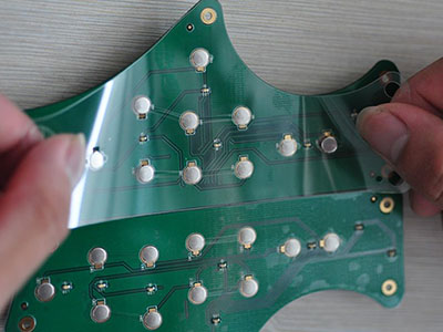
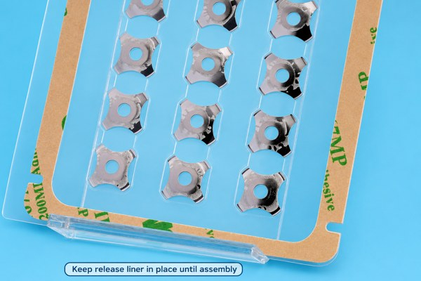
Keep pads protected until the assembly step, inspect the contact area before placement and remove loose process debris with an approved method. Complete contaminating board operations before applying a dome array where the process permits. Maintain the supplied release liner until placement, control operator handling and verify that adhesive edges and vent openings match the drawing. Placement accuracy will not compensate for an unclean contact surface.
Define a check at the process step where a defect is still visible: pad inspection before placement, array-position inspection afterward, and electrical verification at the intended input conditions. If multiple keys or lots fail in the same pattern, stop treating them as isolated rework events. Review cleaning, storage, handling and carrier alignment records together before releasing more units.
For a first-article build, photograph one clean pad and one installed dome at the intended inspection magnification. Use those approved examples to align operators on what a loose fiber, adhesive squeeze-out or shifted carrier actually looks like. The image should support inspection, while the electrical test still determines whether the assembled key meets its specified function.
What Evidence Should Be Recorded Before Release?
Record the affected position, lot, as-found photos, contact geometry, inspection method, electrical test circuit and the original failed result. Distinguish a fiber on a pad from discoloration, damaged plating or adhesive transfer; each leads to a different corrective action. Keep the removed material or suspect dome when failure analysis requires it.
After correction, record what changed, who approved the method and the repeated result against the product’s actual acceptance criteria. A passing result on one actuation, especially at an unspecified meter current, is not enough evidence of stable contact. If the source remains uncertain, mark the root cause unresolved and continue investigation rather than assigning it to contamination by assumption.
Keep disposition separate from root-cause status. A unit can be rejected because it fails the approved electrical test even when the contaminant has not been identified. Conversely, a cleaned unit should not be released solely because a visible particle was removed; release depends on the specified repeat test and any required reliability check for that construction.
| Record | Minimum useful detail | Why it matters |
|---|---|---|
| As-found state | Key position, photo of dome and pads, lot and assembly stage | Preserves evidence before rework |
| Electrical baseline | Supply, pull-up or load, actuation method, repeated results | Makes the failure reproducible |
| Correction | Material removed, part replaced or process adjustment | Separates action from assumed cause |
| Release test | Approved criterion, repetitions and recorded result | Shows whether the actual input requirement was met |
How Do Dome Shape and Array Design Affect Risk?
Different dome shapes place their contact and support regions differently. A round dome and four-leg dome therefore need different pad inspection points and clearance checks; neither is automatically contamination-proof. The drawing must show the contact footprint, allowable alignment and any spacer or vent feature. Inspect the actual supplied configuration rather than applying a generic drawing to every switch.
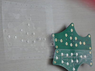
For a peel-and-place array, the carrier can help keep domes positioned and limit direct handling before installation, but an array installed over dirty pads can still trap debris. Choose the supply form and inspection plan together. When you discuss an array with us, share the PCB pad drawing, dome location, film and adhesive stack, assembly sequence and electrical test condition so the contamination controls address the real contact path.
Metal Dome Contact Contamination FAQs
Can a metal dome feel normal but fail electrically?
Yes. A normal snap does not verify pad-to-pad continuity. Compare the failed key and a good key at the actual input conditions, then inspect both contact faces if the response differs.
Will cleaning always fix an intermittent dome contact?
No. Cleaning will not correct a damaged finish, bent dome, shifted array or broken trace. Use only a material-compatible, approved method and retest repeatedly after correction.
For a recurring defect, examine the process that deposits or traps the material. Metal dome contact contamination is a useful diagnosis only when the observed material, contact location and controlled retest support it. At EBest Circuit(Best Technology), we can review the dome or array construction against your pad drawing and failure record. Send those files to sales@metal-domes.com.