
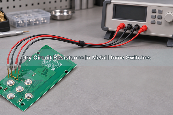
dry circuit resistance is the closed-contact resistance measured with voltage and current low enough to avoid changing the metal dome-to-PCB contact interface. In a low-energy keypad circuit, a normal resistance test can puncture or electrically clean a surface film and produce a value that does not represent the first low-level closure. A valid result therefore depends on the voltage limit, current limit, four-wire connection, actuator condition and test order, not only the number shown in ohms.
What Is Dry Circuit Resistance?
A metal dome closes a circuit when its center contact reaches the PCB center pad while its perimeter remains connected to the outer pad. The measured value includes the constriction at those contact spots, surface films, the PCB finish, conductive paths and any resistance left in the test fixture. A dry circuit resistance measurement keeps the electrical stimulus below the level that could disrupt those films.

This condition matters because a contact can appear acceptable after a higher-energy measurement even though the first low-level closure was unstable. Dry-circuit testing preserves that condition long enough to measure it. It does not mean the contact is literally dry, nor does it describe moisture content.
Why Does a Metal Dome Need a Dry Circuit Test?
A metal dome may switch a logic input, sensing circuit or other low-energy load that cannot rely on current to break through an oxide or contamination film. The tactile click can feel normal while the electrical closure is delayed, intermittent or higher in resistance than expected. A dry circuit resistance test checks that low-level interface before another electrical test changes it.
The test is most useful when the application has a small detection current, a long storage interval, demanding environmental exposure or a tight contact-resistance requirement. It also helps compare PCB finishes, cleaning conditions, dome plating and assembly processes under the same controlled actuation.
Dry Circuit Resistance vs Standard Contact Resistance Testing
| Test | Electrical condition | What it can show | Main risk if misused |
|---|---|---|---|
| Dry circuit resistance test | Low open-circuit voltage and limited current | Low-level closure without intentionally changing the contact film | A loose fixture or inconsistent actuator can be mistaken for contact failure |
| Standard contact resistance test | May use a higher source voltage or current | Resistance after closure under the stated test condition | The stimulus may puncture a film and hide the first-closure condition |
| Continuity test | Instrument-dependent | Whether the circuit is open or closed at a broad threshold | It does not provide a controlled low-level resistance value |
| Functional circuit test | Actual product load | Whether the assembled interface works in its intended circuit | It cannot isolate the dome, PCB pad, fixture and electronics by itself |
A result labeled “contact resistance” is not automatically a dry-circuit result. The record must state the source limits, measurement current, connection method and actuation condition. A value measured at a higher voltage cannot be substituted merely because it is lower or more repeatable.
What Voltage and Current Define a Dry Circuit Test?
A widely used general dry-circuit envelope limits open-circuit voltage to no more than 20 mV and short-circuit current to no more than 100 mA. IEC 60512-2-1 identifies a millivolt-level method for contact resistance, while low-resistance instruments may provide dedicated low-power modes. Some instruments use much less current, so the actual setting must be recorded rather than inferred from the mode name.
| Parameter | Common test control | Why it matters | What it does not prove |
|---|---|---|---|
| Open-circuit voltage | Often limited to 20 mV maximum | Reduces the chance of breaking down a surface film before measurement | It does not set the product operating voltage |
| Short-circuit current | Often limited to 100 mA maximum; many setups use less | Controls electrical energy at the closed contact | It is not automatically the application current |
| Measurement range | Selected for the expected milliohm or low-ohm region | Provides suitable resolution and noise performance | A high displayed resolution does not remove fixture error |
| Integration and settling | Fixed in the test plan | Improves repeatability when readings fluctuate | Averaging must not hide intermittent opens |
These values are test-method controls, not a universal acceptance limit for every circle metal dome. The drawing should name the required standard or provide the exact instrument limits, actuation and pass/fail value.
Why Should Dry Circuit Resistance Be Measured First?
Dry-circuit measurement should precede dielectric, continuity, standard-ohms or functional tests that may apply more electrical energy to the same contact. Mechanical cycling, cleaning, wiping and repeated actuation can also change the interface. Once a film has been disrupted, repeating the low-level test does not reconstruct the original condition.
- Condition the sample only as the approved plan requires.
- Connect the four-wire fixture and verify its zero or reference check.
- Apply the defined center actuation without side load.
- Record the first closure and the required repeat readings.
- Perform higher-energy electrical or functional tests afterward.
- Repeat the same sequence after environmental or life exposure when comparison is required.
The record should preserve the sequence. “Passed contact resistance” is incomplete if it does not show whether a higher-energy test occurred first.
How Do You Measure Dry Circuit Resistance with a Four-Wire Method?
A four-wire resistance measurement uses one pair of leads to source the test current and a separate pair to sense the voltage close to the contact path. The instrument calculates resistance from the sensed voltage and known current. Because little current flows through the sense leads, their resistance does not add directly to the result as it does in a two-wire measurement.
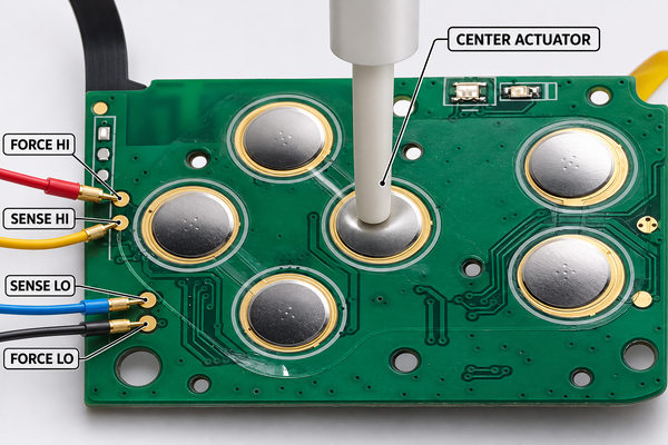
Connect FORCE HI and SENSE HI to one side of the switching path, and SENSE LO and FORCE LO to the other. Place the sense points inside the current-injection points when the PCB layout allows it. A milliohm meter or low resistance measurement instrument must be placed in a true low-power mode; four terminals alone do not guarantee a dry-circuit test.
How Should a Metal Dome Be Actuated During the Test?
Electrical closure must be measured under a defined mechanical condition. Press the dome through the intended actuator location, normally near the center, with a flat or radiused nonconductive tip that represents the product stack. The fixture should reach complete closure without scraping the dome, touching a probe or bending the PCB.
Record the actuator diameter, position, travel or force, hold time and release method. If the project uses a metal dome array, test the dome through the production carrier and adhesive stack when those layers can change alignment or preload. A loose dome on a bench and an installed dome array are not equivalent mechanical conditions.
How Do PCB Pads and Surface Finishes Affect the Result?
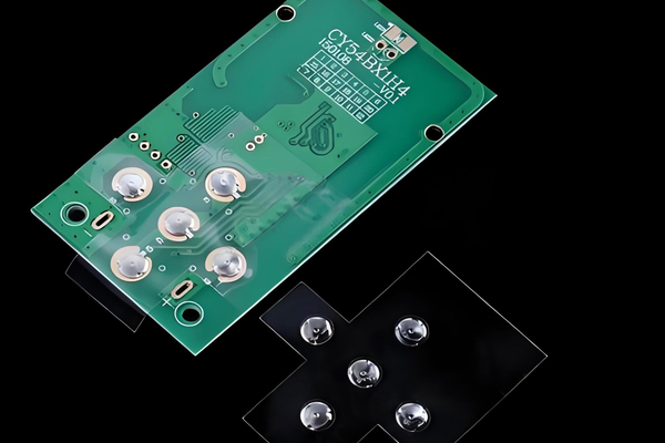
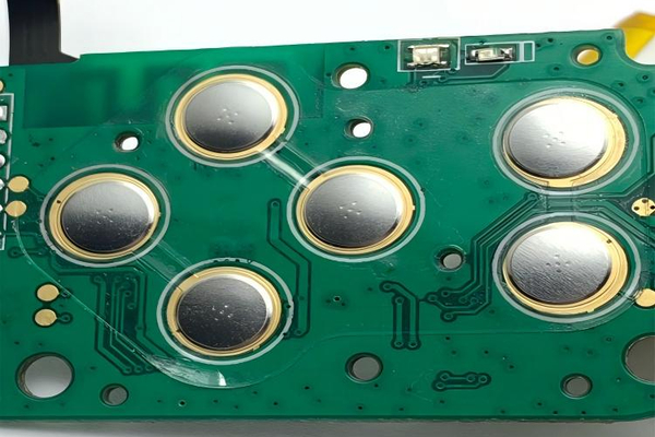
The measured path depends on the dome material or plating, PCB pad finish, exposed area, cleanliness and contact geometry. Gold, nickel-based finishes and other pad systems do not behave identically after storage or environmental exposure. Residue at the center pad, a solder-mask ridge, an uneven outer ring or an unsupported board can create variation that is wrongly attributed to the dome alone.
Specify the finish and pad drawing together with the electrical test. When we review a custom metal dome project, we need the PCB contact layout and surface finish as well as the required dome size and force. The resistance result belongs to the complete contact interface, not to a nominal dome diameter by itself.
What Causes Unstable or Intermittent Resistance Readings?
| Observed result | Likely area to check | Verification action | Possible correction |
|---|---|---|---|
| Reading changes when cables move | Probe, connector or fixture | Lock the actuator and move one connection at a time | Repair the fixture or add strain relief |
| First closure is high, later closures are lower | Surface film, wiping or test order | Use untouched samples and confirm low-power mode | Review finish, storage, cleanliness and sequence |
| Reading changes with actuator position | Off-center load, dome alignment or PCB support | Map the actuator center and inspect the stack | Correct actuator diameter, alignment or support |
| Only one key in an array is unstable | Local pad, adhesive pocket, contamination or dome placement | Compare adjacent keys with the same fixture | Inspect and correct the local assembly |
| All keys shift after humidity exposure | Finish, residue, seal path or test conditioning | Compare pre- and post-exposure data under identical conditions | Review cleaning, storage, sealing and material selection |
Do not average an intermittent open into an acceptable resistance value. The test plan should state whether the peak, first stable value, defined-window average or maximum reading controls acceptance.
How Do You Separate Fixture Error from Contact Failure?
Start with a reference short or known low-resistance artifact that exercises the same cables and instrument range. Confirm the force and sense leads are assigned correctly. Then check the fixture without changing the sample: cable movement, probe pressure, connector oxidation and board flex should not change the reading beyond the allowed fixture variation.
- Record the fixture zero or reference value before the lot.
- Keep sense contacts close to the PCB switching path.
- Use repeatable probe force and a fixed board support.
- Prevent the actuator from touching probes or flexing the board.
- Retest a suspect sample in a second verified station before disposition.
- Preserve raw readings when the failure is intermittent.
Four-wire measurement removes most lead resistance from the voltage reading, but it does not correct an unstable probe, contaminated pad, moving actuator or poor sample support.
How Does Contact Force Change the Measurement?
Resistance can fall as the real contact area increases after full closure. However, a higher applied force is not a substitute for the specified dome and actuator stack. Excess overtravel can deform the dome, flex the PCB or create a result that the product never reaches in service. Too little travel may measure a partially closed contact.
Separate tactile requirements from electrical test conditions. Dome trip force, return force and tactile ratio describe mechanical behavior; dry circuit resistance describes the closed electrical path under a stated actuation. The drawing should connect these conditions without treating one as proof of the other.
How Do You Compare Results Before and After Reliability Testing?
Use the same instrument mode, fixture, actuation, dwell time and calculation method before and after temperature, humidity, storage, vibration or life-cycle exposure. Record individual-key data rather than only a lot average. The useful comparison includes the initial value, final value, absolute change, intermittent events and any failure to close.
Environmental conditioning can change the contact interface, adhesive stack and PCB support at the same time. A post-test increase therefore triggers inspection of the complete assembly. It does not by itself prove that the stainless dome or its plating is the only cause.
What Dry Circuit Resistance Limits Should Go on the Drawing?
There is no single dry circuit resistance limit that can be copied into every metal dome drawing. The acceptable value depends on the circuit threshold, PCB finish, dome finish, mechanical stack, environmental requirement and measurement uncertainty. Define the requirement from the system budget, then confirm it with prototypes and reliability data.
| Drawing or test-plan field | Required entry | Why it is needed |
|---|---|---|
| Test method | Named standard or controlled internal method and revision | Prevents different interpretations of “dry circuit” |
| Electrical limits | Maximum open-circuit voltage and short-circuit or measurement current | Controls whether the contact film can be changed |
| Connection | Two-wire or four-wire, sense-point locations and fixture reference | Defines what resistance is included |
| Actuation | Tip, location, force/travel, dwell and board support | Makes closure repeatable |
| Acceptance | Maximum value, intermittent-open rule and sample plan | Turns readings into an auditable decision |
| Sequence | Dry-circuit test position relative to other electrical tests | Protects the original interface condition |
Dry Circuit Resistance FAQs
Is a continuity test the same as a dry circuit resistance test?
No. A continuity test uses an instrument-specific source and threshold. Unless its voltage, current and resistance method meet the approved low-level conditions, it cannot replace the dry-circuit measurement.
Can a two-wire meter measure dry circuit resistance?
It can use low electrical energy, but lead and fixture resistance become part of the reading. Four-wire measurement is normally preferred when the acceptance value is low enough for those errors to matter.
Does a low resistance reading guarantee reliable field switching?
No. The result confirms one electrical condition under one mechanical and environmental state. The product still needs suitable pad design, actuation, sealing, cleanliness and reliability validation under its actual circuit load.
Should every metal dome be tested at 20 mV and 100 mA?
No. Those values are a commonly used upper envelope for dry-circuit testing, not a mandatory operating point or universal product specification. Use the approved standard, customer drawing and instrument capability for the project.
What Should You Include in a Dry Circuit Test RFQ?
For a custom metal dome or custom dome array, send us the dome or array drawing, PCB pad layout, surface finish, actuator stack, operating load, target resistance, test voltage/current limits, required sample quantity and environmental sequence. Identify whether the value applies to a loose dome, a dome on the production PCB or the complete keypad assembly.
At EBest Circuit(Best Technology), we can review whether the requested geometry, carrier construction and test access are compatible before quotation. If the final assembly is tested by the customer, align the fixture and acceptance record during the prototype stage so both sides compare the same electrical path.