
A metal dome can click normally while its electrical contact remains resistive or intermittent. Wetting current is the current associated with overcoming surface-film resistance at a mechanical contact. A tactile snap confirms movement, not reliable conduction. For a low-power input, check the dome finish, PCB pad finish, available voltage and actual closed-contact current together before changing the pull-up resistor or rejecting the dome.
What Is Wetting Current?
Wetting current is commonly described as the minimum contact current needed to establish reliable conduction through a surface film. The useful engineering value is specific to a contact system and its operating conditions; it is not one current that every switch must carry.
Voltage can initiate film breakdown, while current through the resulting microscopic conducting spots can help establish conduction. Contact force, surface condition and available electrical energy all affect this behavior. A clean contact designed and qualified for low-level signals may operate without a deliberate film-clearing pulse.
Do not confuse wetting current with the maximum switching-current rating. The maximum describes an upper operating limit. It does not prove reliable switching at microampere loads, nor authorize a high-current pulse to restore an unreliable contact.
What Is Wetting Voltage in Metal Dome Switches?
Wetting voltage describes the voltage available across a contact interface to help overcome a resistive film. In a normally open metal dome input, inspect the voltage across the open switch and the current available when it closes. These are different quantities from the small voltage drop across an already conducting contact.
For example, a 3.3 V supply with a 10 kOhm pull-up and a switch to ground provides approximately 0.33 mA after closure, assuming negligible contact resistance and input leakage. A 100 kOhm pull-up reduces that current to approximately 33 microamperes. Both circuits have roughly the same open-switch voltage, but different closed-contact currents.
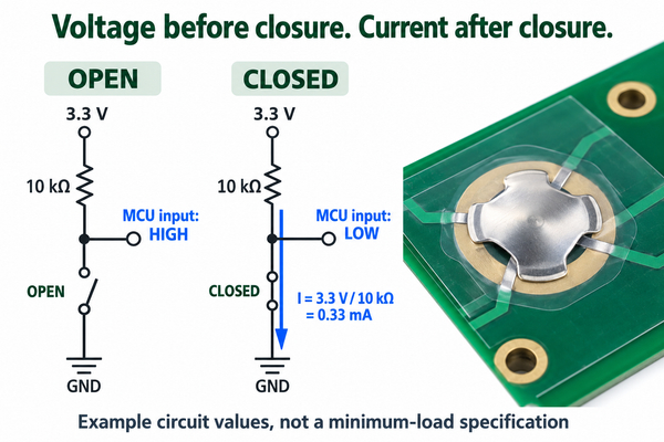
These are circuit calculations, not minimum-load specifications. There is no universal wetting-current formula that predicts film breakdown from supply voltage alone. Adding capacitance or increasing voltage can produce damaging peak current even when average current remains low.
Why Do Dry Circuits Develop Unstable Contact Resistance?
Dry circuits can become unstable because their limited electrical excitation does not necessarily break through oxide, sulfide or contamination films. The apparent contact area is much larger than the microscopic spots that actually carry current, so a small change at those spots can change resistance substantially.
An unplated stainless steel dome has a passive surface film. Silver-containing contacts can develop sulfide films in suitable environments. Flux residue, adhesive contamination, handling oils and particles can also interfere with conduction. These mechanisms require different corrective actions; increasing current is not a substitute for identifying contamination or inadequate contact pressure.
With a metal dome, the electrical path includes both the center contact and the outer support contact. Misalignment, poor seating or an actuator that does not complete the intended travel can affect either interface. A click with no stable input transition therefore requires both mechanical and electrical checks.
What Is Dry Circuit Resistance?
Dry circuit resistance is contact resistance measured with excitation limited enough to avoid significantly changing the surface film. It describes the measurement conditions, not a separate resistance material or a guarantee that the contact will work in every low-power circuit.
Separate the test quantities before comparing supplier results.
| Quantity | What it tells you | What to specify |
|---|---|---|
| Dry circuit resistance | Contact behavior under limited test excitation | Open-circuit voltage limit, current limit, fixture and actuation condition |
| Resistance at application load | Contact voltage drop at the actual operating current | Supply, current waveform, sampling time and input thresholds |
| Maximum switching load | Upper permitted switching conditions | Rated voltage/current combination, load type and life conditions |
| Minimum applicable load | Low-load operating reference for a defined contact system | Exact part, mating finish, environment and reliability criterion |
Common dry-circuit measurement practice uses limits such as 20 mV open-circuit voltage and 100 mA short-circuit current. These are test-method ceilings, not a recommended operating pair, minimum wetting voltage or minimum switching current. Agree on the actual test method and any stricter limits before using results for acceptance.
How Do Contact Material and Plating Change Low-Current Reliability?
Contact material and plating change the films that form, the exposed surface and its response to repeated operation. Gold resists oxidation and is often considered for low-level contacts, but plating continuity, wear and the mating PCB surface still determine performance.
Use the finish comparison to select a test candidate, not to assign a universal minimum current.
| Contact choice | Low-current consideration | Qualification boundary |
|---|---|---|
| Unplated stainless steel | Passive film can affect small-signal conduction | Verify first closure and resistance after storage at the actual load |
| Nickel-plated contact | Nickel surface behavior differs from a gold contact surface | Do not treat nickel as a low-load substitute without equivalent test evidence |
| Silver-plated contact | Sulfur exposure can introduce resistive tarnish | Match environmental exposure and low-load testing to the intended use |
| Gold-plated contact | Reduced oxidation risk can benefit small-signal switching | Confirm coverage, thickness, underplate, wear life and mating finish |
Our four-leg metal domes include different surface-finish configurations. Select the specific part and finish against the circuit conditions rather than assuming that every finish in the series has identical low-current performance.
How Do You Specify Gold Plated Contacts for Low Current?
Specify the entire mating pair, not just a gold-colored dome. A drawing that says only “gold plated” leaves the contact area, minimum thickness, underplate and wear requirements unresolved.
For gold plated contacts for low current, include:
- Dome contact-area finish, minimum plating thickness, underplate and any selective-plating boundaries.
- PCB pad finish and thickness, exposed contact geometry, cleanliness requirements and protection during assembly.
- Actual voltage, minimum and maximum closed-contact current, and any startup or capacitor-discharge pulse.
- Resistance acceptance limit, test excitation, first-closure requirement, storage exposure and required operating cycles.
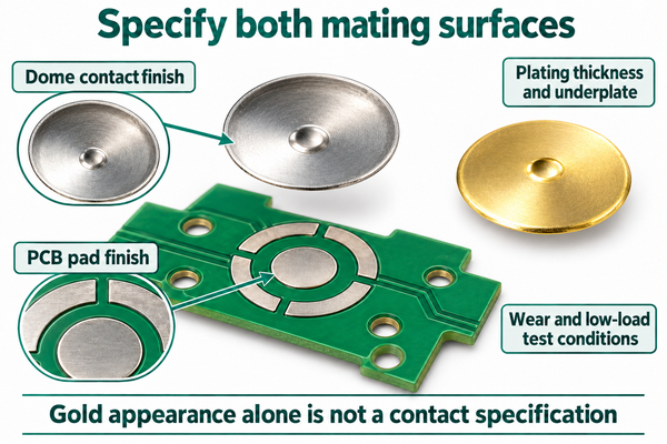
PCB ENIG, hard gold and other gold-bearing finishes are not interchangeable descriptions of a finished contact system. Evaluate the actual stack and mating conditions. Do not add an arbitrary gold thickness to a purchase order without a wear and low-load requirement that justifies it.
For a custom metal dome, provide the pad drawing and actuator arrangement with the electrical requirements. Changing geometry or force can change the contact conditions even when the finish stays the same.
What Is the Minimum Switching Current for Metal Dome Switches?
There is no single minimum switching current for all metal dome switches. A usable low-load specification must identify the dome part, both contact finishes, voltage, actuation conditions, environment and acceptance criterion. A maximum-current rating alone cannot answer this question.
If a datasheet does not state a minimum applicable load, treat low-current suitability as unverified, not automatically unsuitable or unlimited. Ask for data at the intended voltage/current combination, including first operation after storage and performance after the required life cycling.
For a scanned keypad, record the peak contact current and how long it flows during each scan. A low average current does not describe the instantaneous electrical conditions. Conversely, a brief current pulse does not prove the contact will remain reliable during the next long idle period.
How Should You Measure Contact Resistance at Low Test Current?
Measure contact resistance at low current with a controlled source, a defined voltage limit and a fixture that does not alter the dome’s seating or contact force. Use four-wire sensing where lead and fixture resistance would materially affect the result, with separate force and sense connections to each side of the switch path.
- Preserve the as-received or failed condition. Do not repeatedly press, scrape or electrically condition the contact before the first measurement.
- Define source-current and open-circuit voltage limits. Check the instrument’s behavior before connection and during switching, not only its nominal resistance range.
- Actuate with the intended alignment, force and travel. Sense across the switch terminals or PCB contact nets without pressing a probe onto the dome’s switching surface.
- Record the first-closure value, subsequent closures, open events and settling time. Apply agreed resistance and input-recognition criteria.
- Test at the actual circuit load separately, then repeat after the specified storage, environmental and life-cycle exposures.
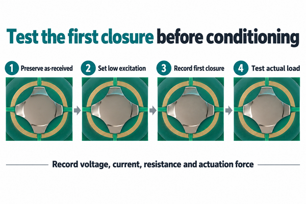
Perform the limited-excitation measurement before higher-energy electrical tests. An ohmmeter or conditioning pulse can change the interface and make a later low-current result appear better than the original condition. Keep mechanical preconditioning and first-closure electrical testing as separate, explicitly documented procedures.
Why Can a Continuity Test Hide an Intermittent Contact?
A continuity test can hide an intermittent contact because its test voltage or current may differ from the application, and its beep threshold may accept much more resistance than your acceptance limit. A slow display can also miss brief openings that the controller detects.
Before using a continuity meter as evidence, check its open-circuit voltage, test current, threshold and response time. Capture the input-pin voltage during real actuation with an appropriate high-impedance measurement, and correlate it with the contact test. Keep the measurement’s added capacitance and loading in the test record.
If a stored sample starts working after several presses or a meter check, retain an untouched sample for comparison. That symptom suggests a condition-sensitive interface; it does not by itself prove inadequate wetting current or justify increasing the load.
How Do You Design a Metal Dome Input for Low-Current Signals?
Design low current switch contacts as a matched mechanical interface and input circuit. Choose a contact system qualified for the proposed load, then check worst-case input recognition, current limits and idle power.
For a pull-up input switched to ground, the approximate closed-input voltage is Vinput = Vsupply x Rcontact / (Rpull-up + Rcontact) when leakage is negligible. Use the controller’s guaranteed input-low threshold, not a nominal switching point. Add resistor tolerances, input leakage, temperature and any matrix-driver resistance to the worst-case calculation.
A calculated logic threshold is not an acceptable lifetime resistance specification by itself. A drifting contact can still have enough margin to pass a static logic check while showing unstable operation. Specify both electrical recognition and contact-resistance behavior.
Lowering the pull-up resistance increases closed current and power consumption; confirm the part’s limits before making that change. If using a controlled pulse, define its peak current, duration, repetition and current-limiting path. Debounce handles contact chatter, not a sustained resistive film. Increasing debounce time cannot repair a contact that never reaches a valid logic level.
Our custom dome arrays can align domes with a supplied PCB or FPC layout. For low-current prototypes, validate the assembled carrier, actuator and mating pads together rather than qualifying loose domes on a different test surface.
Why Does a Metal Dome Switch Fail at Low Current?
A low-current failure can come from the contact interface, mechanical assembly or input circuit. Use an untouched sample and the real operating load to distinguish these causes before changing the finish or current.
| Symptom | Possible cause | Measurement | Corrective action |
|---|---|---|---|
| Clear click, input stays high | Film resistance, contamination or incomplete center contact | First-closure resistance plus input voltage during full actuation | Identify the interface problem; correct cleanliness, seating or qualified finish |
| First press fails after storage | Storage-related film or contamination | Compare untouched samples before and after defined storage | Control storage and handling; qualify both mating surfaces |
| Meter beeps, controller misses presses | Different excitation, loose beep threshold or missed brief openings | Compare meter conditions with actual waveform and timing | Use application-level acceptance and adequate acquisition bandwidth |
| Intermittent switch contact at low current improves with harder pressing | Off-center actuator, pad alignment or inadequate travel | Correlate force/travel with resistance | Correct actuator and stack tolerances; do not substitute excessive force |
| Failures appear only during keypad scanning | Scan dwell, drive current, leakage or settling mismatch | Capture contact current and input voltage within the scan window | Adjust timing or circuitry within qualified contact limits |
| Good initial result, drift after cycling | Wear, exposed underplate or debris | Repeat low-load tests and inspect worn contact regions | Reassess finish, contact pressure and life requirement |
Changing one factor at a time makes the result usable. A simultaneous change to plating, force and pull-up resistance may restore function without identifying which condition caused the failure.
FAQ
1. Does a dry contact mean a dry-circuit-rated contact?
No. A dry contact commonly means a contact that does not supply its own voltage, often called a volt-free contact. Dry-circuit suitability describes behavior at limited electrical excitation. Confirm the minimum-load conditions separately.
2. Is sealing current the same as wetting current?
In some electrical-contact and telecommunications discussions, sealing current refers to current used to maintain a conductive contact or connection. The term is context-specific. It does not mean environmental sealing, and a relay coil’s seal-in or holding current is a different requirement.
3. Does whetting current mean something different?
“Whetting current” is a common misspelling of wetting current in switch discussions. It does not define a separate electrical parameter.
4. Can I add a capacitor across the switch to improve conduction?
A capacitor can deliver a transient current when the contact closes, but peak current is limited by the complete discharge path, not the pull-up resistor alone. Check capacitance, ESR, wiring resistance, voltage and contact ratings before testing. Do not use an uncontrolled discharge as a production remedy.
5. Is a mechanical life rating enough for a battery-powered keypad?
No. Mechanical life does not establish electrical reliability at your low-load conditions. Require valid input recognition and contact-resistance acceptance during the relevant cycling and after idle or storage periods.
6. Should every low-current dome be gold plated?
No. A different finish may be adequate when it passes the required low-load and environmental tests. Gold adds cost and still needs a defined mating surface and wear requirement; select it for demonstrated reliability needs, not appearance.
Reliable wetting current selection starts with a defined contact pair and verified operating conditions, not a universal milliampere rule. At EBest Circuit(Best Technology), we manufacture standard and custom metal domes and dome arrays. Send the dome or pad drawing, contact finishes, circuit voltage/current, actuator details and low-load acceptance requirements to sales@metal-domes.com so we can review the appropriate prototype configuration with you.