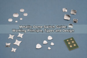

Dome Array Adhesive Design and Testing connects the adhesive pattern on the drawing with the way the finished keypad is assembled and verified. A sound bond must hold the carrier in position without contaminating the contacts, obstructing the air path or restricting dome movement. Qualification therefore needs both adhesive specimens and complete working keys: high peel strength alone does not prove that a keypad will return correctly after repeated presses.

What Should a Dome Array Adhesive Drawing Specify?
Specify the bonded areas, adhesive-free areas and positioning references separately. The overall array outline does not tell an assembler where adhesive is allowed or how far a cutout may move relative to a contact pad.

Use a common datum system for the PCB, dome centers, carrier outline and adhesive cutouts. Identify which surface the adhesive actually touches: solder mask, coverlay, bare laminate or another coating. A material description such as FR4 does not identify the finished bonding surface.
Drawing item
What to define
What to check on a sample
Bonding surface
Finish, coating and permitted cleaning process
Actual production surface, not just a laboratory metal panel
Adhesive pattern
Bonded regions, openings and prohibited overlap
No adhesive in electrical contact or moving regions
Location
Datums, dome centers and cutout tolerances
Worst-case relative position, including placement error
Layer construction
Carrier, adhesive and spacer thicknesses separately
Delivered stack, excluding the removable liner
Air path
Openings, channel route and endpoint
Route remains open after lamination and enclosure assembly
Release liner
Peel direction, tabs and split locations if used
Removal without stretching or lifting the carrier
Keep the adhesive specification and drawing revision together. A replacement dome adhesive with a similar description is still a material change, not an automatic equivalent. For choosing between adhesive families, our dome array adhesive selection article covers the material-selection step.
Where Should Adhesive Be Kept Away from a Metal Dome?
Keep adhesive out of the electrical contact area and any region that must move freely. Define the keepout from the actual dome and pad geometry, then account for cutting, placement and board-registration tolerances. The apparent gap in a nominal drawing is not necessarily the remaining gap in an assembled key.
Consider a hypothetical drawing with a 0.40 mm nominal clearance. If the allowed relative shifts toward the contact are 0.10 mm from die cutting, 0.15 mm from array placement and 0.05 mm from the board reference, the simple worst-case clearance is 0.10 mm. This is a tolerance example, not a recommended dome clearance; any adhesive flow allowance would reduce it further. The design must establish whether the remaining clearance is sufficient.
Our double-layer dome arrays include a spacer and air paths. For that construction, check the adhesive cutout against the spacer channel rather than assuming that a visible opening in the top film proves the whole route is open. Enlarging a keepout also reduces nearby bond area, so verify the narrow adhesive lands between adjacent keys.
How Can Adhesive Thickness Change the Keypad Feel?
Adhesive thickness changes the installed stack and can alter how the retaining film is supported. It must be considered together with carrier stiffness, spacer height, dome geometry and the actuator's rest position. A thicker adhesive is not simply a stronger version of a thinner one.
In our single-layer dome arrays, metal domes are retained beneath adhesive PET film with vent openings. Adding an extra bonding layer changes that construction. Compare the assembled force-travel response before accepting the change, including release and return, not just the force needed to make the first click.
Separate adhesive thickness from total tape thickness in the specification. Do not count the release liner as part of the installed keypad. For dome strips spanning several keys, check both end keys and interior keys because their supported film areas may differ.
How Should You Control Dome Array Lamination?
Use a defined preparation and application sequence, with controlled positioning, pressure and dwell. For pressure-sensitive adhesive, initial tack is not the same as the bond after a specified dwell period. The material's application guidance and the actual assembly establish the conditions; there is no single pressure or waiting time that suits every array.
- Verify the board surface, cleanliness and dryness before exposing the adhesive.
- Locate the array against the drawing references without stretching the PET.
- Remove the liner in the specified direction, keeping fingers and loose liner fragments away from the bond surface.
- Apply the validated pressure to the supported bonding regions. Avoid an uncontrolled load through the domes.
- Inspect for wrinkles, trapped air, lifted edges, blocked vents and displaced domes.
- Record the dwell before handling, testing or installing the next keypad layer.
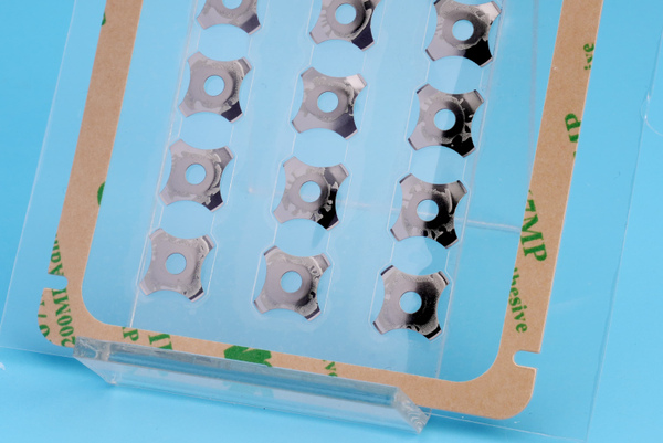
The release liner protects the adhesive before placement; it is not evidence that the adhesive has bonded to the PCB. If a key is repositioned after contact, segregate that sample from the first-placement group. Otherwise, the trial mixes normal assembly with rework and the cause of a weak bond becomes unclear.
Which Samples Do You Need for Adhesive Testing?
Use flat adhesive specimens to compare bond behavior and complete dome arrays to check the functioning assembly. Make both with the intended material lots and preparation process. A smooth reference panel can help compare tape batches, but it cannot establish adhesion to a different production solder mask.
| Sample group | Purpose | Important controls |
|---|---|---|
| Flat peel specimen | Compare separation resistance | Strip width, backing, substrate, angle, speed and dwell |
| Shear specimen | Assess movement under sustained loading | Bond area, load, temperature and duration |
| Complete keypad | Check retention and switching together | Actual actuator, support, overlay and electrical circuit |
| Unexposed control | Distinguish exposure effects from normal variation | Same material and assembly batch |
Plan sample quantities and acceptance rules before testing. Keep lot identities and assembly records with each specimen. Do not use the same destructively peeled sample for a later functional qualification. When a narrow bond land is the design concern, include that feature in an assembly sample rather than testing only a wide, easy-to-bond strip.
How Do You Measure Adhesive Peel Strength?
Measure the force required to peel the specified strip at a controlled angle and speed, and report the result relative to strip width. For pressure-sensitive adhesive testing, ASTM D3330 provides peel-adhesion methods; the selected method, edition and any deviations must be identified in the test plan. A hand pull is useful for spotting an obvious problem, but it is not a repeatable peel measurement.
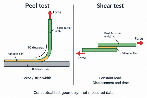
Keep the peel geometry consistent. Results from 90-degree and 180-degree tests are not interchangeable. Record the substrate, dwell and conditioning along with the force trace. Note whether separation occurs at the board surface, within the adhesive, at the carrier interface or through damage to the substrate.
For example, an average force of 3 N on a 10 mm strip is 0.30 N/mm, or 3 N/cm. This arithmetic example is not a pass limit. An increased reading caused by a stiffer backing or a different test angle does not, by itself, demonstrate a better dome-array bond.
Why Do You Need a Shear Test as Well as a Peel Test?
A shear test addresses sliding under a load parallel to the bond. Peel testing addresses separation from an edge. An adhesive can resist one loading condition while moving under another, especially when temperature and loading time change.
For a static shear assessment, define the bonded area, applied load, temperature, duration and allowable displacement or failure endpoint. ASTM D3654 covers shear-adhesion test methods for pressure-sensitive tapes; use the appropriate agreed procedure instead of treating all shear tests as equivalent.
Relate the loading to the keypad design. A flat, well-supported carrier and a carrier held under tension by a flex tail do not impose the same demands on the bond. Check whether creep could move a dome, narrow a vent or expose an edge even before the specimen separates completely. Record displacement and failure mode, not only whether the sample fell off.
How Should You Test Adhesion after Heat, Humidity and Cleaning Exposure?
Choose exposures from the keypad's actual use and storage conditions, then repeat the relevant bond and functional checks. Record whether measurements are made during exposure, immediately afterward or after recovery. Those are different conditions and should not be combined into one result.
For a frequently wiped control panel, specify the real cleaning fluid, concentration, contact time and application method. For a warm enclosure, consider the installed bond temperature and sustained stress rather than only the room-temperature peel value. Include unexposed controls so a change in the test fixture is not mistaken for an environmental effect.
Inspect edge lift, bubbles, adhesive transfer and any movement toward the contact region. Strong adhesion after a short exposure does not establish a waterproof rating or a service-life claim. Test any required ingress protection on the complete enclosure and keypad construction, including vent endpoints.
How Do You Check Tactile and Electrical Performance after Bonding?
Check dome actuation, release and electrical closure on the completed keypad before and after the planned exposures and cycles. Adhesive tests cannot detect every problem caused by trapped air, film tension or local preload.
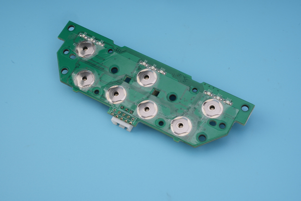
A dome tester or force-displacement instrument should use a defined actuator position and supported board. Compare force-travel curves, return behavior and closure position using the same setup. Test representative edge and interior keys; include keys next to narrow adhesive lands or difficult vent routes.
Measure the electrical contact under specified test current and voltage conditions. Record missed closures and intermittent events rather than relying only on the tactile click. If a newly laminated keypad feels different from the reference, check the layer thickness, air path and film strain before changing the dome force. An adhesive change may have altered the assembly even though the metal dome itself is unchanged.
What Acceptance Criteria Should a Dome Array Meet?
Set separate acceptance criteria for the bond, array geometry and switching function before testing. Passing an average peel requirement must not cancel a failed key or an adhesive overlap onto a contact.
| Check | Define before the trial | Record with the result |
|---|---|---|
| Peel | Method, width-normalized limit and conditioning | Force trace and separation location |
| Shear | Load, area, duration and displacement limit | Movement, time and failure mode |
| Geometry | Placement and adhesive-clearance limits | Before/after images against the drawing |
| Tactile response | Permitted actuation and return behavior | Force-travel data under the same fixture settings |
| Electrical function | Resistance and interruption criteria | Measurement settings and individual key results |
Do not average away an isolated failure on a critical key. Retain the failed sample before cleaning or peeling it apart, and compare it with a matched control. If the result falls outside the planned limit, identify whether the cause is material, surface preparation, geometry, application or test setup before approving a revised design.
When Does a Dome Array Need Adhesive Requalification?
Requalification is needed when a change can affect the bond or key behavior. Relevant changes include adhesive grade or thickness, carrier construction, solder-mask or coverlay surface, cleaning chemistry, cutout pattern, lamination equipment and enclosure loading. A change confined to the board supplier can still change the bonding surface.
Compare the changed characteristic with the original failure risks and repeat the affected tests. If more than one factor changes, keep a controlled reference configuration so the results remain interpretable. Update the drawing and acceptance record together; a passed trial on an undocumented construction cannot reliably control later production.
At EBest Circuit(Best Technology), we manufacture custom dome arrays with specified outlines, dome locations and cutouts. For a new array, send the board layout, bonding-surface details, layer drawing, operating environment and required test criteria to sales@metal-domes.com. We accept drawing formats including PDF, AutoCAD and Gerber; include the expected quantity and any restrictions on adhesive substitutions so the quotation covers the intended construction.
Dome Array Adhesive Design and Testing FAQs
Can release-liner removal force be used as peel strength?
No. Liner release measures separation from the protective liner, not the final bond to the PCB. Keep liner handling checks separate from substrate adhesion results.
Does a higher peel value always make a better keypad?
No. The array must also maintain its position, return freely and switch electrically. A change that raises a peel value can still create an unsuitable stack thickness or strain the carrier.
Can you reuse an array after peeling it from the board?
Do not assume it retains the original qualification. Removal can stretch the carrier, contaminate the adhesive or disturb the domes. Treat reuse as a separate, explicitly validated rework process.
Should every test specimen contain a metal dome?
No. Flat specimens help isolate adhesive behavior, while complete dome switches reveal assembly effects. Both are needed when bond performance and key function are part of the requirement.
Dome Array Adhesive Design and Testing is complete only when the specified construction meets its bond, placement and switching criteria under the intended conditions. Keep the drawing, assembly method and test record linked so a successful prototype can be reproduced in production.