Metal dome membrane switch suppliers can provide loose stainless-steel domes, pre-positioned dome arrays, or engineering support for integrating the tactile layer into a membrane switch. The useful distinction is not the supplier label but the controlled scope: dome geometry, force curve, carrier film, adhesive, venting, actuator interface, dimensional inspection, and production testing. This guide explains how those elements fit together so a switch design can move from a tactile target to a repeatable assembly.
What Do Metal Dome Membrane Switch Suppliers Actually Supply?
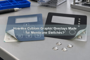
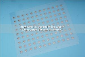
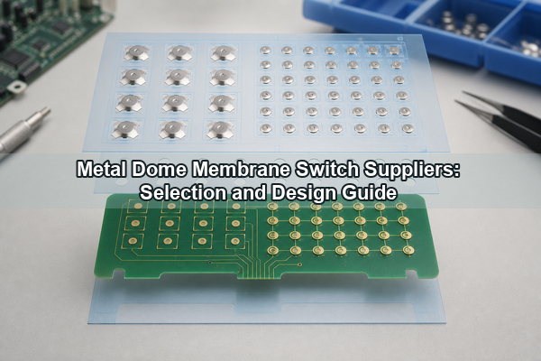
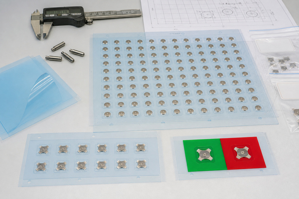
The supply boundary can stop at the dome or extend through the complete tactile subassembly. A loose metal dome is a formed stainless-steel contact that bridges the center and outer PCB contacts when pressed. A dome array positions multiple domes on an adhesive PET or Mylar carrier so their X-Y coordinates, rotation, and retention are controlled before installation. A complete membrane-switch project can add the printed circuit, graphic overlay, spacer, shielding, backlighting, tail, connector, and enclosure interface.
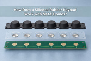
These scopes are not interchangeable. Loose domes suit automated or controlled manual placement where the circuit assembler owns alignment and retention. A custom dome array is more appropriate when key coordinates, mixed dome forces, unusual outlines, registration holes, or assembly speed matter. When a supplier does not build the complete membrane switch, the drawing package still needs to define the interfaces between the dome array, circuit, overlay, actuator, and housing.
EBest Circuit(Best Technology) has manufactured metal domes and metal dome arrays since 2006. Its published range includes single-layer, double-layer, EMI-printed, rubber-glue, LGF, plunger, and custom dome arrays. That portfolio is relevant because each construction solves a different integration problem; selecting an array type should follow the stack-up rather than a generic preference.
Which Parts of the Membrane Switch Stack-Up Define Supplier Scope?
A metal dome membrane switch is a system of mechanical and electrical tolerances. From top to bottom, a typical stack may include a graphic overlay, overlay adhesive, embossed or flat key area, actuator or plunger, spacer, dome-retaining film, metal dome, printed circuit, rear adhesive, and support plate. Some designs combine layers, while others add shielding or a light guide.
The critical interface is the distance from the underside of the overlay or actuator to the dome apex. Excess clearance creates a soft pre-travel before the dome is engaged. Insufficient clearance preloads the dome and can reduce tactile ratio, raise resting stress, or cause intermittent contact. The support beneath the circuit must also be rigid enough to prevent local flex from absorbing dome travel.
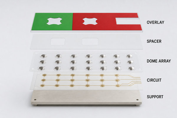
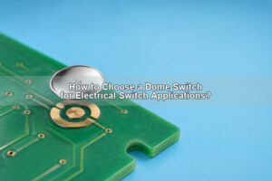
The circuit contact pattern is equally important. A round dome normally bridges a central contact and a surrounding ring; four-leg and triangle domes use outer contact regions matched to their feet. The center pad must remain electrically isolated from the outer contact, and the dome must not cover solder mask steps, vias, debris traps, or uneven surface features that disturb seating.
Which Dome Geometry and Force Range Fit the Interface?
Dome selection begins with available footprint, required force, travel, key size, actuator shape, acoustic target, and circuit-pad geometry. Circle domes provide a compact, symmetric response. Four-leg domes offer stable seating and can accommodate vent paths between the legs. Triangle domes suit compact layouts with three contact points, while oblong domes fit elongated keys or constrained footprints.
Trip force alone does not define key feel. A complete tactile specification should include nominal force, tolerance, travel, return force, snap ratio, dome diameter or outline, dimple configuration, and the force measured through the finished overlay or actuator. A higher force can resist accidental operation, but a stiff overlay or small actuator may make the assembled key feel substantially heavier than the loose-dome measurement suggests.
| Design variable | Engineering effect | What to verify |
|---|---|---|
| Dome geometry | Controls footprint, seating, contact pattern, and available vent path | Pad layout, rotation, enclosure clearance |
| Trip force | Sets the force at snap-through | Finished-key force, not only loose-dome force |
| Travel | Determines displacement before contact closure | Overlay and actuator stroke allowance |
| Snap ratio | Influences the sharpness of tactile feedback | Force-displacement curve and sample feel |
| Dimple pattern | Changes contact interface and local pressure | Pad finish, current level, contamination control |
For custom programs, use measured samples to establish the assembled force curve. A nominal loose-dome value is useful for initial selection, but final acceptance should be based on the actual stack-up, keycap or overlay, circuit support, and test speed.
How Do Single-Layer and Double-Layer Dome Arrays Differ?
A single-layer metal dome array holds domes with one adhesive carrier layer. It minimizes thickness and component count, making it suitable when the circuit is clean and flat, venting is handled by the PCB or carrier pattern, and the surrounding assembly provides adequate protection.
A double-layer metal dome array adds a spacer or second film structure around the domes. The extra layer can define an air channel, reduce adhesive contact with the dome, improve retention, and protect the tactile element during handling. It also adds thickness, material interfaces, and tighter control of cutouts and registration.
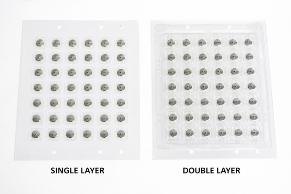
Choose the simplest construction that meets the environment and assembly requirements. A thicker array is not automatically more reliable; reliability depends on adhesive compatibility, clean air movement, correct cutout geometry, flat application, and stable support beneath the circuit.
How Should Adhesive, Venting and Actuator Alignment Be Designed?
The adhesive must bond to the circuit or membrane substrate throughout temperature, humidity, cleaning, and handling without flowing into the dome cavity. The surface-energy match, adhesive thickness, liner release, die-cut edge quality, storage condition, and application pressure all affect long-term retention. Rubber-glue constructions are useful where the array must accommodate a rougher surface or a specific bonding requirement, but the adhesive still needs compatibility testing on the actual substrate.
Venting prevents trapped air from resisting dome movement or slowing recovery. Air can move through channels in a spacer, gaps between dome legs, dedicated PCB vias, or a connected cavity. Vent routes should not become paths for liquid or contamination. For sealed products, the pressure equalization strategy must be considered together with enclosure sealing rather than added after the keypad geometry is fixed.
Actuator alignment controls load direction. The actuator should press near the dome center with a contact face wide enough to avoid a point load but small enough to stay inside the active dome area. Side loading, oversized key rock, or an off-center plunger can distort the force curve and shorten service life. For molded keys or rigid caps, a plunger dome array can fix the load point and reduce tolerance accumulation.
What Quality Tests Should a Supplier Control?
Incoming material checks and in-process controls should verify dome dimensions, carrier thickness, adhesive condition, registration, dome orientation, contamination, and cut-edge quality. Force testing should capture trip force and rebound force with a defined fixture, probe geometry, speed, and support condition. Without a consistent method, results from two laboratories may not be comparable even when the domes are identical.
Life-cycle testing needs the assembled interface or a representative fixture. The test should use the specified actuation force, stroke, frequency, temperature, and acceptance criteria. Electrical verification can include contact resistance, bounce, continuity, and insulation between the center and outer contacts. Visual inspection after cycling should look for cracking, permanent deformation, adhesive migration, dome displacement, and wear at the contact points.
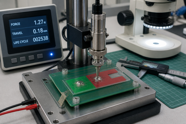
EBest Circuit(Best Technology) lists trip-force measurement, rebound-force measurement, and life-cycle testing among its production controls. For ordinary double-layer, EMI, rubber-glue, and LGF arrays, the published total-height range is 0.28–0.45 mm and the published force scope is 100–400 gf; the final capability depends on dome geometry, stack-up, adhesive, circuit layout, environment, quantity, test method, and engineering review.
Which Applications Benefit Most From Metal Dome Membrane Switches?
Metal dome membrane switches are most useful when the interface needs a clear momentary click in a thin package. Industrial controls use the tactile event to confirm operation in repetitive tasks. Medical equipment can use it to distinguish an intentional keypress from incidental contact. Automotive interior controls benefit where an operator must locate and activate a physical key without watching the surface continuously.
Handheld instruments, payment terminals, appliance controls, access panels, test equipment, and communication devices also use dome arrays. The application should determine the force and protection strategy. Gloves, vibration, cleaning agents, UV exposure, temperature cycling, backlighting, and enclosure stiffness can each change the appropriate construction.
A metal dome is unnecessary when the interface requires continuous position sensing, a completely silent non-tactile surface, or analog force measurement. It is also a poor correction for an unstable overlay, flexible support, misaligned actuator, or contaminated contact design. Those system issues need to be resolved at the stack-up level.
When Are EMI, Rubber-Glue, LGF and Plunger Arrays Useful?
Special array constructions add a specific function and should not be treated as generic upgrades:
- EMI metal dome arrays add a shielding-related conductive layer or printed feature where the keypad stack participates in electromagnetic control.
- Rubber-glue metal dome arrays support applications that need a different bonding behavior from standard pressure-sensitive adhesive.
- LGF dome arrays combine a light-guide film with the tactile layer to distribute illumination across keys while preserving a thin stack.
- Plunger arrays add a controlled actuator above each dome for rigid keycaps, molded rubber keys, or tightly defined load transfer.
Each option changes thickness, tolerances, material interfaces, tooling, and inspection. The stack drawing should therefore identify which function is required, the target total height, the surrounding materials, and the surfaces to which the array will bond.
How Do Metal Dome Membrane Switch Suppliers Support Prototypes and Production?
Prototype support should turn design intent into controlled manufacturing data. Useful inputs include circuit artwork, key coordinates, dome type, nominal force and travel, overlay or actuator geometry, array outline, registration features, vent paths, adhesive zones, connector orientation, and operating conditions. Missing dimensions should be resolved before array tooling because carrier and spacer geometry directly determine dome position.
EBest Circuit(Best Technology) can develop custom arrays from AutoCAD, PDF, Gerber, PCB, CAM, and other PCB files, with engineering review also available for customer drawings. Early samples should be used to measure the finished-key force curve, check dome-to-pad registration, confirm liner removal and application, and inspect key-to-key consistency.
For production, revision control must cover dome material and geometry, force classification, film and adhesive, die-cut files, array orientation, inspection method, packaging, and lot identification. A change to the overlay, actuator, support plate, or PCB finish can alter tactile performance even when the dome part number remains unchanged.
How Can Supplier Capabilities Be Compared Without Over-Specifying the Design?
Compare capabilities against the design variables that can cause failure or inconsistency. A useful review checks whether the supplier controls dome forming, force sorting, carrier and adhesive conversion, array registration, contamination, dimensional inspection, force-displacement testing, life cycling, and revision traceability. It should also clarify whether the supplier owns only the dome array or coordinates the circuit, overlay, backlighting, and final assembly interfaces.
Avoid specifying a familiar dome shape or force before the pad layout, key size, available height, actuator, and support stiffness are known. Instead, define the functional targets and physical constraints, then verify the proposed construction with measured samples. This approach preserves room for a manufacturable geometry while keeping acceptance criteria objective.
The same logic applies when evaluating metal dome membrane switch suppliers: compare evidence from drawings, samples, process controls, and test records rather than relying on a broad product description.
FAQ About Metal Dome Membrane Switch Suppliers
What is a metal dome membrane switch?
It is a momentary switch assembly that places formed metal domes over conductive contact patterns within a membrane-switch stack. Pressing a dome creates tactile snap and closes the circuit; releasing it restores the dome and opens the contact.
What is the difference between a loose dome and a dome array?
A loose dome is installed individually. A dome array pre-positions one or more domes on an adhesive film, controlling location, orientation, and handling as one assembly.
Should dome force be measured before or after assembly?
Both measurements are useful, but the finished-key force curve is the final design reference because the overlay, actuator, adhesive stack, circuit support, and enclosure can change the force perceived at the key surface.
Can one dome array contain different shapes or forces?
Yes, a custom array can combine positions with different dome sizes, geometries, or force classes when the carrier layout and assembly controls clearly identify each location.
Can a dome array be applied to PCB, FPC, or a membrane circuit?
Yes. Peel-and-place arrays can be designed for rigid PCB, flexible printed circuit, or printed membrane circuits, provided the adhesive, pad design, venting, flatness, and support structure match the substrate.
How early should the dome supplier review the stack-up?
Review should occur before array tooling and before the overlay or actuator geometry is frozen. Dome diameter, apex height, travel, force, vent path, and actuator clearance are coupled dimensions.
Conclusion
A reliable metal dome membrane switch depends on more than choosing a dome force. Geometry, pad layout, carrier construction, adhesive, venting, actuator alignment, support stiffness, inspection, and assembled-force testing must work as one controlled stack. The supplier scope should match the interfaces the project needs to control, from loose domes through custom arrays and specialized EMI, LGF, rubber-glue, or plunger constructions.
For engineering review of a dome-array stack, contact EBest Circuit(Best Technology) through the custom metal dome and dome array contact page.