
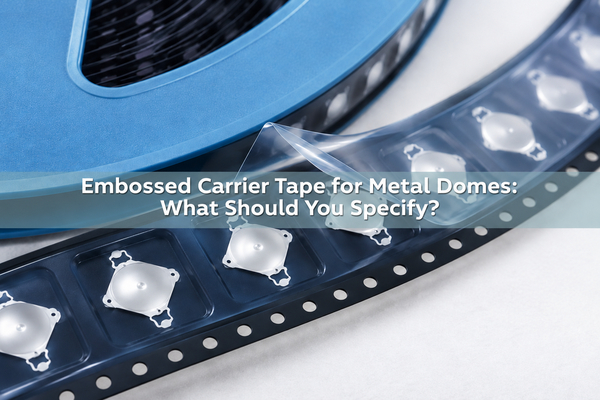
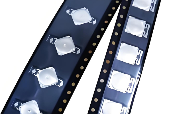
Embossed carrier tape for metal domes holds each spring dome in a formed pocket under a removable cover film. It protects the part in shipment and presents a repeatable pickup position to a reel feeder. The pocket must fit the dome’s actual legs and crown, while the cover film must open without dragging the dome out. We supply tape-and-reel metal domes; the approved dome drawing and the customer’s feeder requirements determine the final package specification.
What Is Embossed Carrier Tape for Metal Domes?
An embossed carrier is a continuous tape with individual recessed pockets. One metal dome is placed in each intended pocket, a cover tape seals over the openings, and the tape is wound onto a reel. At assembly, the feeder indexes the sprocket holes, peels back the cover tape and exposes one dome for pickup. Unlike a flat adhesive dome array, the metal dome carrier tape does not attach the dome to the circuit after release.

This is a presentation and protection format, not a change in the dome’s electrical construction. Our standard loose metal domes are not made solderable simply by packing them for an SMT-style feeder. The circuit still needs the specified contact pattern and dome-retention method.
How Does a Metal Dome Sit in an Embossed Pocket?
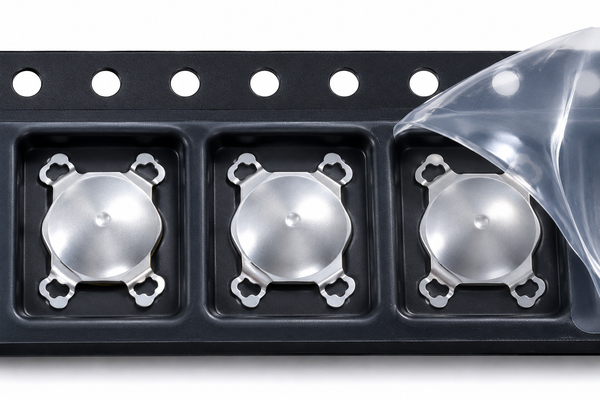
The pocket supports the part without crushing the crown or catching a leg. A dome that can rattle excessively may rotate, tip or arrive off-center under the pickup head. A pocket that grips the edge too tightly can retain the dome when the nozzle lifts or can bend the legs as the tape advances. For a four-leg dome, check the outer leg envelope as well as the nominal crown diameter.
The cover film spans the cavity; it should not be the feature that holds the spring down. Inspect actual samples after winding, shipping simulation and opening, because a drawing alone does not show whether the dome climbs a wall, sticks to the film or changes shape.
Which Pocket Dimensions Belong on the Drawing?
Carrier tape pocket design starts with the controlled dome outline, not a generic catalog pocket. A0 and B0 describe the pocket opening in the two plan directions; K0 describes the formed depth. The drawing also needs the tape width, pocket pitch, sprocket-hole location, seal lands and tolerances appropriate to the selected tape supplier and feeder. Use the exact dimension definitions on the approved drawing rather than assuming every supplier labels its views the same way.
| Drawing item | Check against the dome or feeder | Likely failure if wrong |
|---|---|---|
| A0 / B0, pocket opening | Overall leg-to-leg envelope, intended rotation and pickup position | Edge snag or excessive movement |
| K0, pocket depth | Crown height, leg support and cover-film clearance | Compression or tipping |
| Pocket pitch and tape width | Feeder index and pickup-head travel | Missed or offset pickup |
| Seal lands | Cover-film bond outside the usable cavity | Film contact with the dome or weak seal |
Do not copy a numerical clearance from a different dome. A small round dome, a four-leg dome and a triangle dome do not have the same limiting feature, even if their advertised nominal sizes look similar.
How Do Dome Shape and Orientation Affect Pocket Design?
Round domes may have little visual orientation in plan view, but their convex and contact sides still matter. A four-leg metal dome has a directional leg envelope; a triangle dome adds a defined angular orientation. The approved drawing should show which face points toward the pocket floor, where the first leg or corner points relative to the sprocket-hole edge, and which face the pickup head sees after cover-tape removal.
Our published tape-and-reel page gives the bottom face touching the pocket as its default presentation, with revised orientation available. That page is a supply example, not permission to skip an orientation view on a new part. Confirm the presentation against the actual switch stack and the assembly line before the production reel is released.
How Is the Cover Tape Sealed Without Touching the Dome?
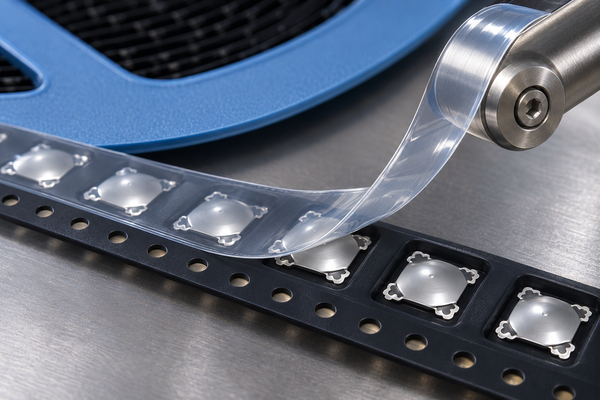
The seal is made on the carrier’s side lands, outside the cavity. A consistent seal keeps pockets closed through handling and transport. A seal path that runs into the pocket can press the crown, trap a leg or transfer adhesive to a part. The cover film also needs a clean peel path at the feeder so the opening action does not tug on the dome.
Cover-tape material and sealing method are chosen with the actual carrier and packaging supplier. The selection must be checked on the assembled tape, including after the specified storage and shipping conditions; a film data sheet by itself cannot prove a stable seal on a formed tape.
What Is Carrier Tape Peel Force?
In this package, carrier tape peel force is the force needed to separate the cover tape from its sealed lands as the reel is opened. It is not the actuation force of the metal dome and not the adhesive peel force of a dome array. Too little seal strength can let the film lift during handling. Too much force, or large force spikes, can jerk the tape, shake a shallow dome or overload the feeder’s peel mechanism.
A useful requirement is a measured force window for the specified tape-and-film combination, not a universal number copied from an unrelated component. The acceptable range also depends on tape width, seal method, feeder geometry and how the packaged domes behave during real pickup.
How Should Cover-Tape Peel Force Be Measured?
Fix a representative section of sealed tape, peel the film using the angle and speed defined for that project, and log force across the measured length. Record the test fixture, tape width, peel angle, speed, conditioning, sample position on the reel and the chosen summary values. Mean force alone can hide a short spike that disturbs one dome; inspect the force trace and the opened pockets together.
Test at least the beginning, middle and end of a trial reel when the seal process may vary along its length. After the peel, check for lifted or tilted domes, film residue and damaged legs. The drawing must name the acceptance method and limits for that package revision; our public product page does not publish a standard peel-force range for every metal dome.
How Do Tape Pitch and Reel Direction Match the Feeder?
Pocket pitch sets the feeder’s advance for each pickup. Tape width and sprocket-hole position locate the tape laterally; winding direction determines which way the domes arrive under the head. Even when the pocket holds the part correctly, the reel can fail on the customer’s machine if any of these interfaces is wrong. Show a feed-direction arrow and a first-pocket orientation view on the packaging drawing.
For two published examples, our reel page pairs an 8.4 mm dome with 16 mm tape and a 12.2 mm dome with 24 mm tape. These are examples for those formats, not a rule that diameter alone selects tape width. The dome envelope, pocket, film seal lands and available feeder all have to fit together.
What Packaging Defects Can Stop Dome Pickup?
At the reel, look for empty pockets, rotated or nested domes, damaged legs, incomplete seals, film adhesive over a cavity, irregular pocket forming and torn sprocket holes. At the feeder, distinguish a dome left in the pocket from one picked but not released. Those two failures require different corrections. A bent leg can also be created upstream during loading, rather than by the placement head.
| Observed symptom | First package check | Trial evidence |
|---|---|---|
| Dome remains after pickup command | Pocket grip, film residue, exposed pickup face | Image of opened pocket and missed-pick count |
| Dome tips as film opens | Pocket depth, excess free play, peel-force spike | Force trace paired with feeder video |
| Intermittent index error | Pitch, sprocket-hole integrity and reel direction | Feeder alarm position and tape segment |
| Leg damage in unopened reel | Loading contact and pocket wall geometry | Incoming sample before feeder use |
How Do You Validate a Pocket with Real Metal Domes?
Start with the approved part revision and a small package trial. Compare incoming domes to domes taken from pockets at the start and end of the reel. Inspect the crown, contact side and legs; then run the tape through the intended feeder at its actual peel path and pickup setting. Count attempted pockets, missed pickups, rotated parts, damaged parts and accepted placements separately.
Include a stop and restart, a reel refill and the storage condition expected before use. Those events can reveal a tape that feeds acceptably for one uninterrupted minute but loses alignment or seal stability in normal production. Finally, test the assembled switch against the customer-approved electrical and tactile requirements. A clean pocket does not by itself prove a working switch.
What Should the Tape-and-Reel Specification Include?
A usable specification for embossed carrier tape for metal domes identifies the metal dome part and revision, drawing of the pocketed tape, permitted presentation orientation, cover-film and seal method, peel-force test conditions and limits, reel direction, leader/trailer requirements, quantity, inspection points and package revision. State which dimensions are critical to the customer’s feeder. If the tape supplier proposes a change to A0, B0 or K0, the revised pocket should be trialed with the real dome before it replaces the approved reel.
Keep package approval distinct from switch-performance approval. The reel can be mechanically compatible while the selected dome or PCB contact geometry still needs its own electrical and tactile validation.
What Do We Need to Prepare a Metal Dome Reel Sample?
Send us the dome drawing or part number, required actuation characteristics, target quantity, desired pocket orientation and the feeder’s tape width, pitch, reel and peel-path requirements. If the feeder is not yet selected, include the intended pickup method and the circuit contact drawing. We can review the dome and tape-and-reel supply together, then agree which dimensions and trial checks belong on the package drawing.
When a reel is unsuitable for the line, our tube-packed metal domes are another documented supply route. The choice should follow the actual handling method, not an assumption that tape is automatically best for every volume or geometry.
Embossed Carrier Tape FAQs
Does tape-and-reel packaging make a metal dome solderable?
No. The carrier changes how a dome is shipped and picked. A standard loose snap dome still needs the intended switch-contact and retention design; solderability depends on the part construction, not the reel.
Can the same pocket be used for round and four-leg domes?
Not without checking the full dome envelope, orientation, depth and pickup face. Similar nominal diameters do not prove equal pocket clearance.
Is cover-tape peel force the same as dome-array adhesive peel force?
No. Cover-tape peel force concerns the seal opened at the feeder. Array adhesive peel concerns separation of an adhesive carrier or liner during a different assembly method.
For a reel sample and package review, send the dome drawing, feeder requirements, expected quantity and requested orientation to sales@metal-domes.com. At EBest Circuit(Best Technology), we can confirm the available supply route and prepare a quotation against the agreed specification.