A keyboard is more than a simple input tool. It is a daily interface that shapes how users feel, respond, and perform. Behind every key press lies a carefully engineered structure, and the metal dome array plays a critical role in delivering a reliable and satisfying tactile response. For manufacturers and designers, understanding how a keyboard metal dome array works—and how it can be optimized—opens the door to better product performance and user satisfaction.

At EBest Circuit (Best Technology), years of experience in precision metal dome manufacturing have shown that small structural decisions can create a noticeable difference in typing comfort, durability, and consistency.
How does a metal dome array improve typing feel in membrane keyboards?
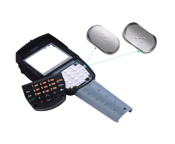
Typing feel is one of the most important aspects of any keyboard. While membrane keyboards are known for their slim design and cost efficiency, they often rely on metal dome arrays to deliver a more defined tactile response.
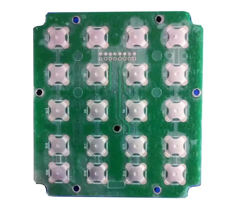
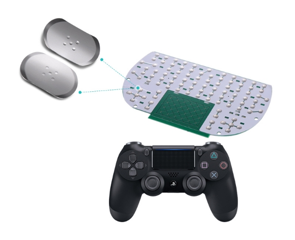
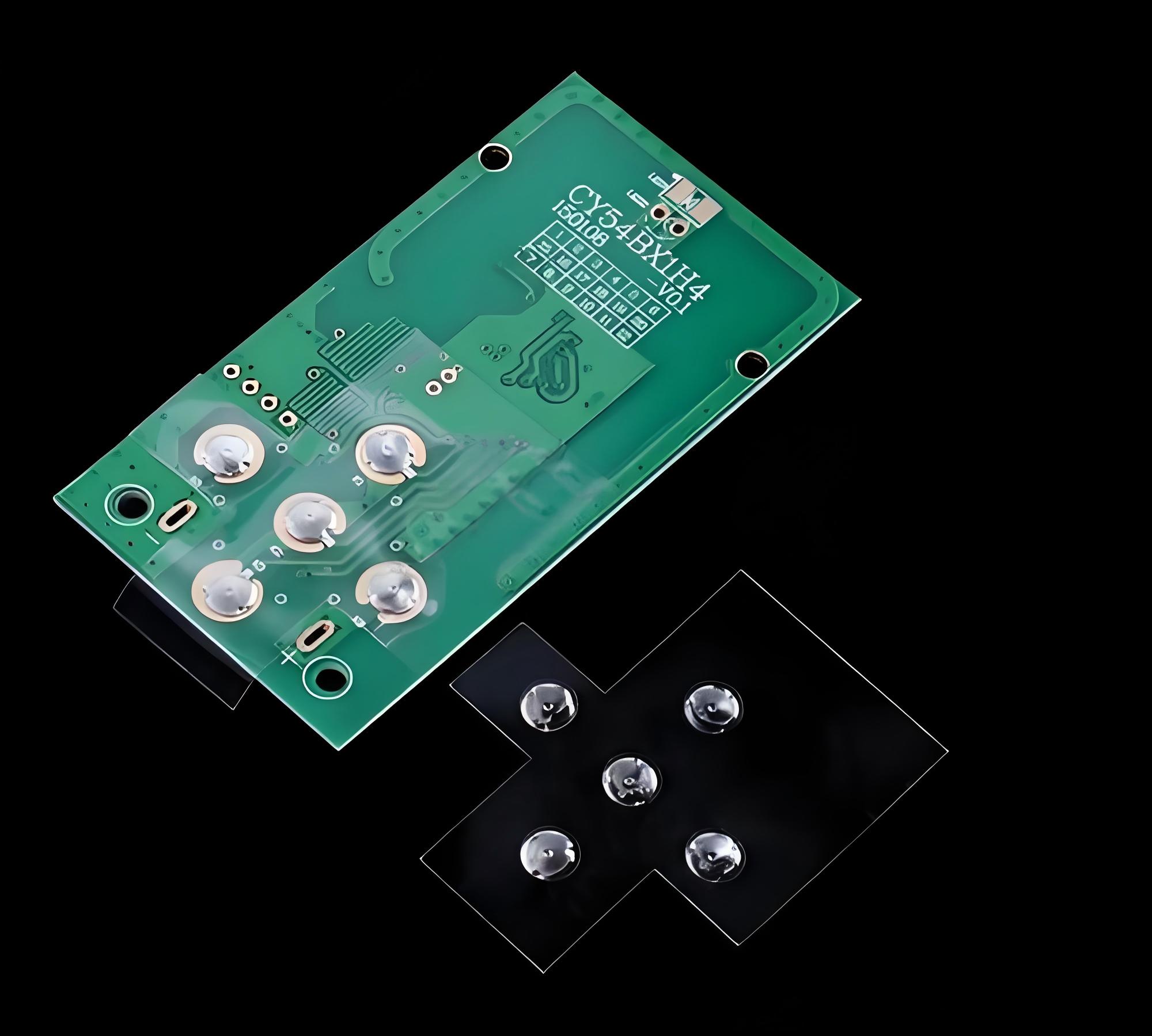
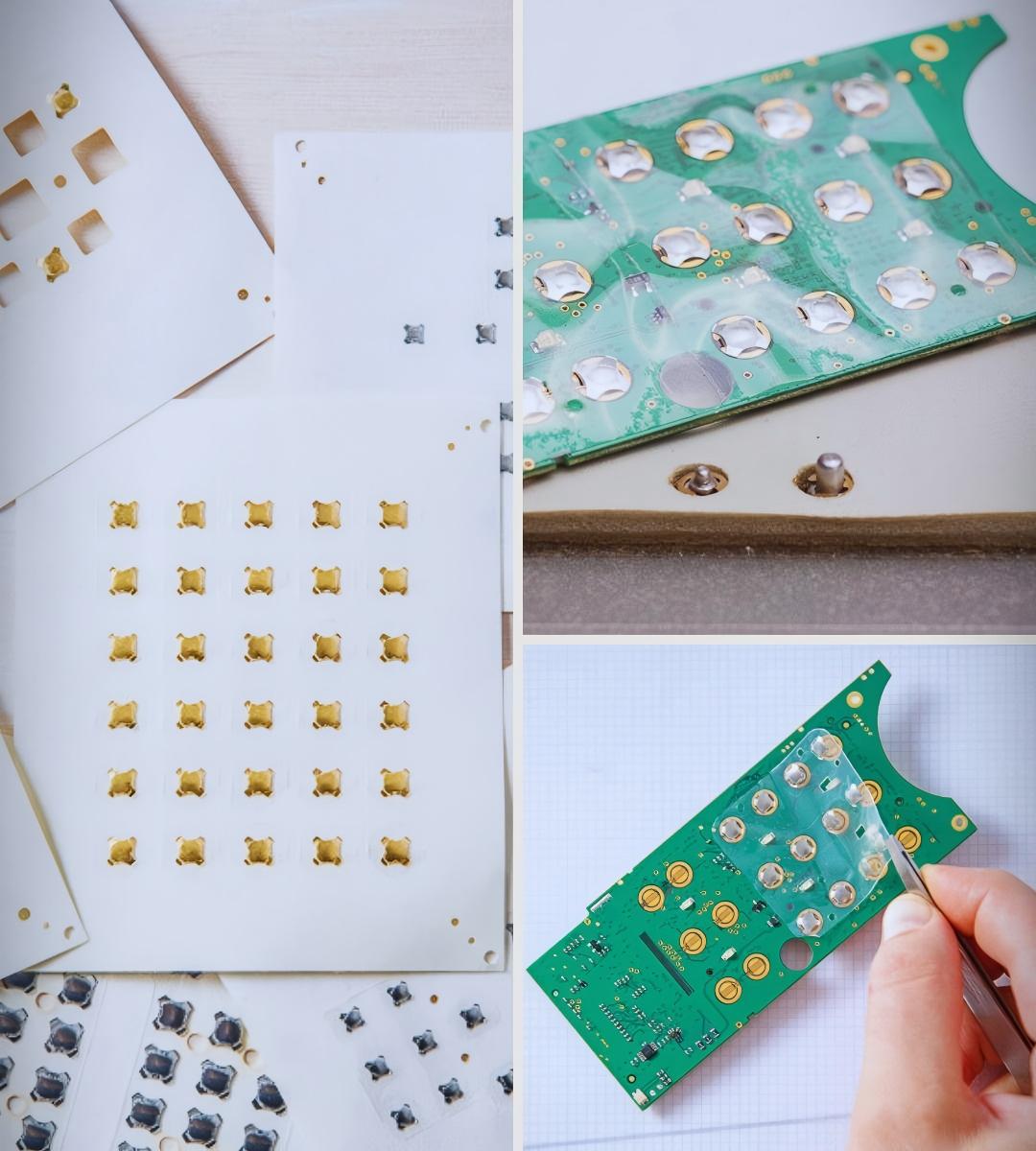
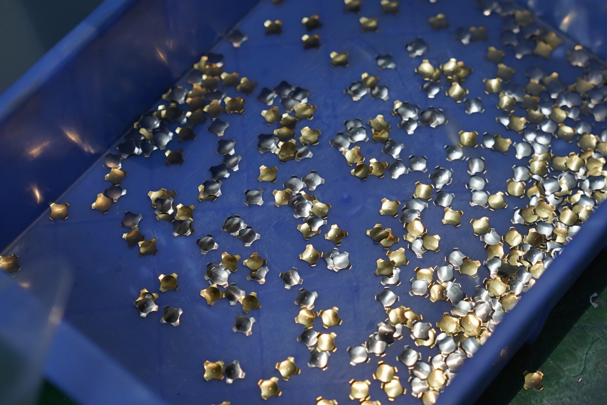
A metal dome array consists of multiple stainless steel domes arranged in a fixed layout on a carrier film. Each dome acts as a switch that collapses under pressure and snaps back to its original shape when released. This snap action creates a tactile bump that users can clearly feel.
The improvement in typing feel comes from several factors:
- Clear tactile feedback
Each key press produces a crisp response, allowing users to confirm actuation without needing to bottom out the key. - Consistent force curve
The dome’s structure ensures that the actuation force remains stable across repeated presses. - Fast rebound speed
The metal dome quickly returns to its original shape, enabling rapid typing without lag. - Reduced finger fatigue
Because users can feel the actuation point clearly, they do not need to press harder than necessary.
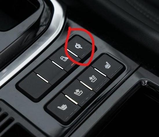
Compared to traditional rubber domes, metal domes provide a sharper and more responsive feel. This is especially valuable in applications where precision matters, such as industrial control panels, medical devices, and compact keyboards. In practice, a well-designed metal dome array can transform a standard membrane keyboard into a high-performance input solution that feels responsive and reliable.
What layout customizations are possible for keyboard metal dome arrays?
Customization is one of the strongest advantages of metal dome arrays. Unlike standard switch modules, these arrays can be tailored to match specific keyboard designs, both in structure and function.
Design flexibility allows engineers to optimize space, improve usability, and meet unique product requirements. Several key customization options are commonly used:
- Dome shape and size
Round, four-leg, and triangle domes are available, each offering different tactile characteristics and stability. - Actuation force variation
Different keys can use domes with different force levels, such as lighter keys for typing and heavier ones for function keys. - Array layout design
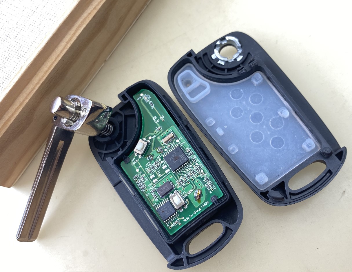
The arrangement of domes can match any keyboard layout, including compact, split, or custom industrial designs. - Circuit alignment
The dome array can be precisely aligned with PCB contact points for accurate electrical performance. - Embossed carrier films
The PET film holding the domes can include embossed features to improve positioning and tactile consistency.
To better understand customization options, the following table highlights key differences:
| Customization Aspect | Standard Design | Customized Array |
|---|---|---|
| Layout flexibility | Fixed patterns | Fully adaptable |
| Actuation force | Uniform | Variable per key |
| Dome shape | Limited | Multiple options |
| Alignment accuracy | Moderate | High precision |
| Application scope | General use | Specialized devices |
EBest Circuit (Best Technology) supports OEM and ODM projects, allowing customers to define exact specifications. This flexibility ensures that each keyboard achieves optimal performance for its intended use.

How to ensure consistent actuation force across a full keyboard dome array?
Consistency is essential in keyboard design. Users expect every key to feel the same, and even small variations can affect the typing experience. Achieving uniform actuation force across a full array requires careful control of several factors during design and production.
First, material selection plays a key role. High-quality stainless steel with stable elasticity ensures that each dome behaves predictably under pressure. Variations in material thickness or hardness can lead to inconsistent force levels.
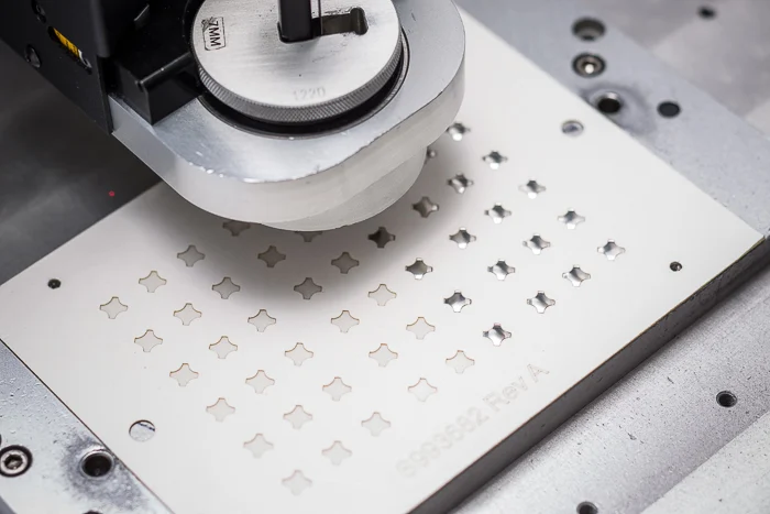
Second, manufacturing precision must be tightly controlled. Advanced stamping processes are used to maintain uniform dome geometry. Even slight deviations in dome height or curvature can affect the force curve.
Third, array assembly must be accurate. The positioning of each dome relative to the PCB contact pads is critical. Misalignment can change the effective actuation force and reduce reliability.
Key methods to ensure consistency include:
- Tight tolerance control during stamping
- Automated inspection systems for dome geometry
- Precise adhesive placement for stable positioning
- Electrical testing for actuation validation
EBest Circuit (Best Technology) applies strict quality control processes, including force testing and lifecycle validation, to ensure that every dome in an array meets the same performance standard. Consistency not only improves user experience but also enhances product reliability over time.
What role does adhesive backing play in keyboard metal dome array performance?
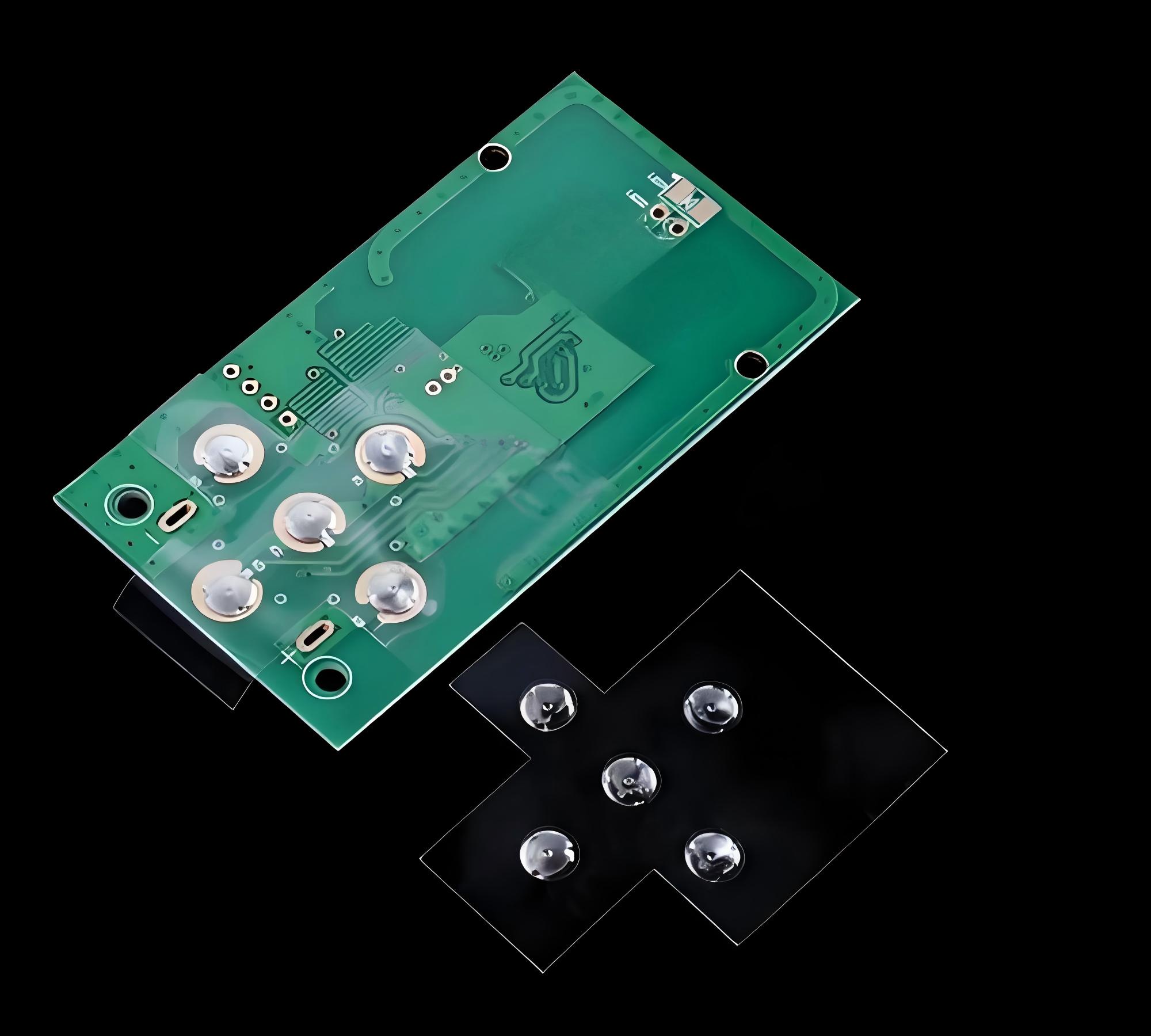
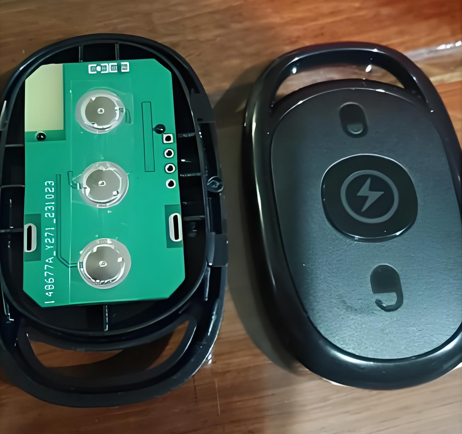
Adhesive backing is often overlooked, yet it plays a vital role in the overall performance of a metal dome array. The adhesive layer secures the domes in place and ensures proper alignment with the circuit. Without a reliable adhesive system, even a perfectly designed dome cannot perform consistently.
The main functions of adhesive backing include:
- Position stability
It prevents domes from shifting during assembly or use. - Accurate alignment
It keeps each dome centered over its corresponding contact pad. - Shock resistance
It helps maintain performance under vibration or mechanical stress. - Ease of assembly
It simplifies the integration process, especially for automated production lines.
Different adhesive materials can be used depending on the application. For example, high-temperature adhesives are suitable for devices exposed to heat, while low-residue adhesives are preferred for sensitive electronics. Selecting the right adhesive ensures long-term reliability and stable tactile performance.
A comparison of adhesive types is shown below:
| Adhesive Type | Key Feature | Typical Use |
|---|---|---|
| Acrylic-based | Strong bonding | General electronics |
| Silicone-based | Heat resistance | Automotive and industrial |
| Low-tack adhesive | Easy removal | Prototyping |
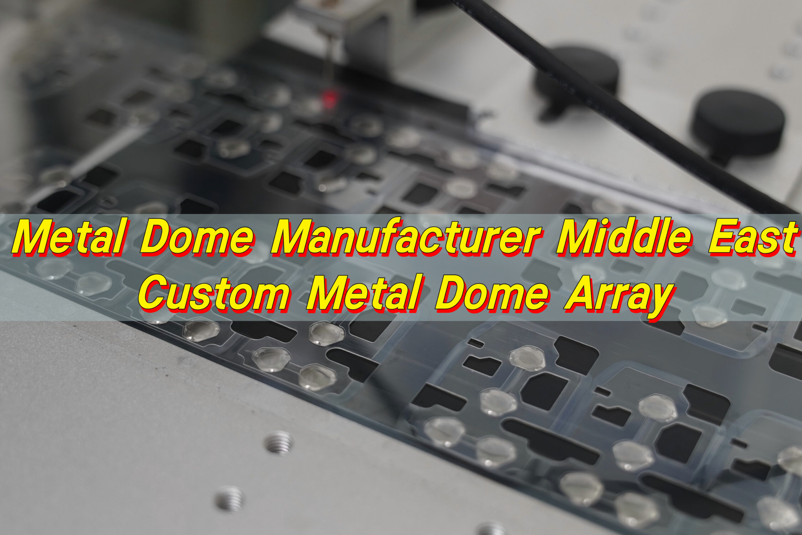
How are metal dome arrays optimized for high-speed SMT assembly?
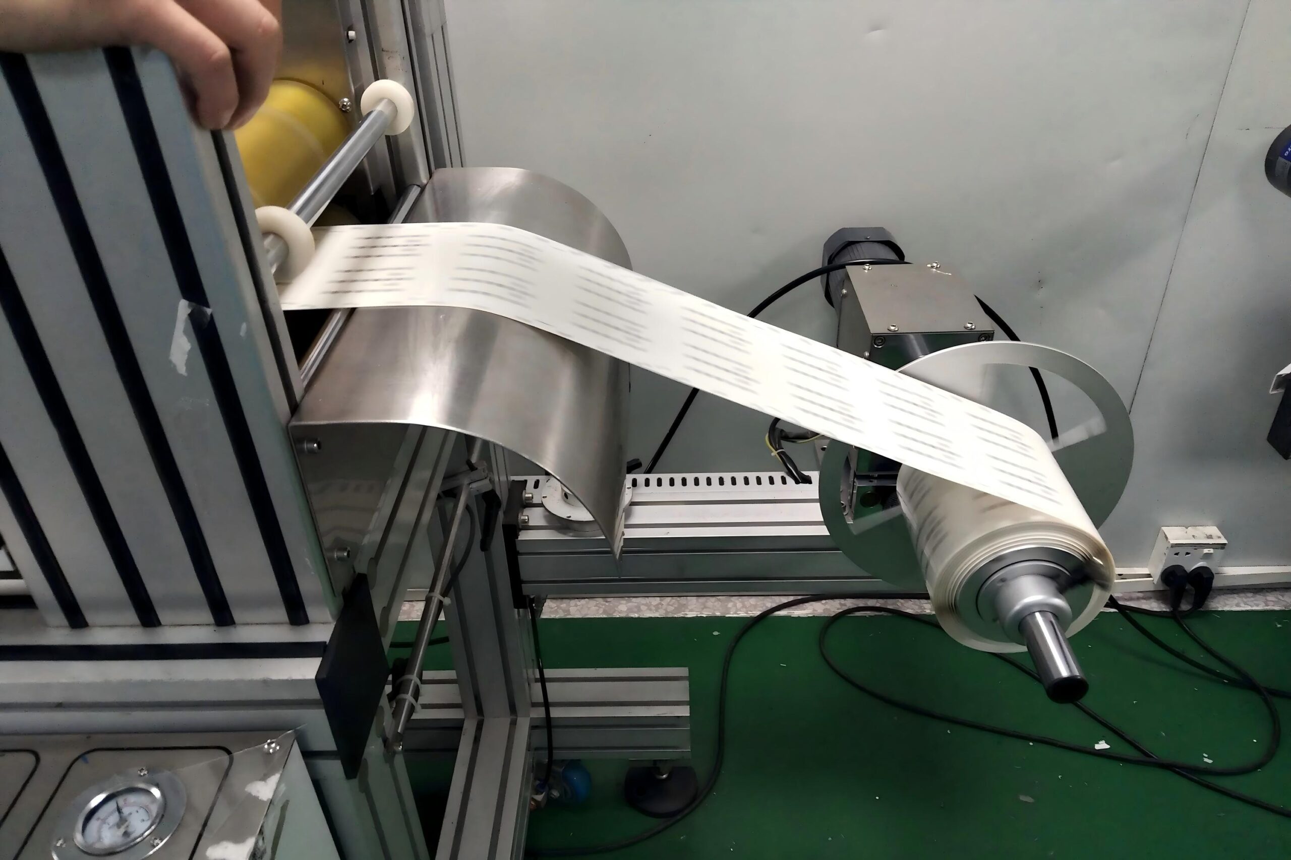
Modern electronics manufacturing demands speed and efficiency. Metal dome arrays are designed to integrate seamlessly into high-speed SMT (Surface Mount Technology) processes. One of the most effective solutions is Tape & Reel packaging. This method allows metal domes to be handled like standard electronic components during automated assembly.
Key advantages of SMT-optimized dome arrays include:
- High placement speed
Machines can place thousands of domes per hour with high accuracy. - Improved alignment
Pre-oriented domes ensure correct positioning during placement. - Reduced labor cost
Automation minimizes manual handling and errors. - Consistent quality
Machine placement ensures repeatability across large volumes.
EBest Circuit (Best Technology) offers Tape & Reel packaging with precise orientation control, enabling efficient mass production. This approach significantly improves assembly efficiency and reduces production time. For manufacturers aiming to scale production, SMT compatibility is not just an advantage—it is essential.

What pitch and spacing standards apply to keyboard metal dome arrays?
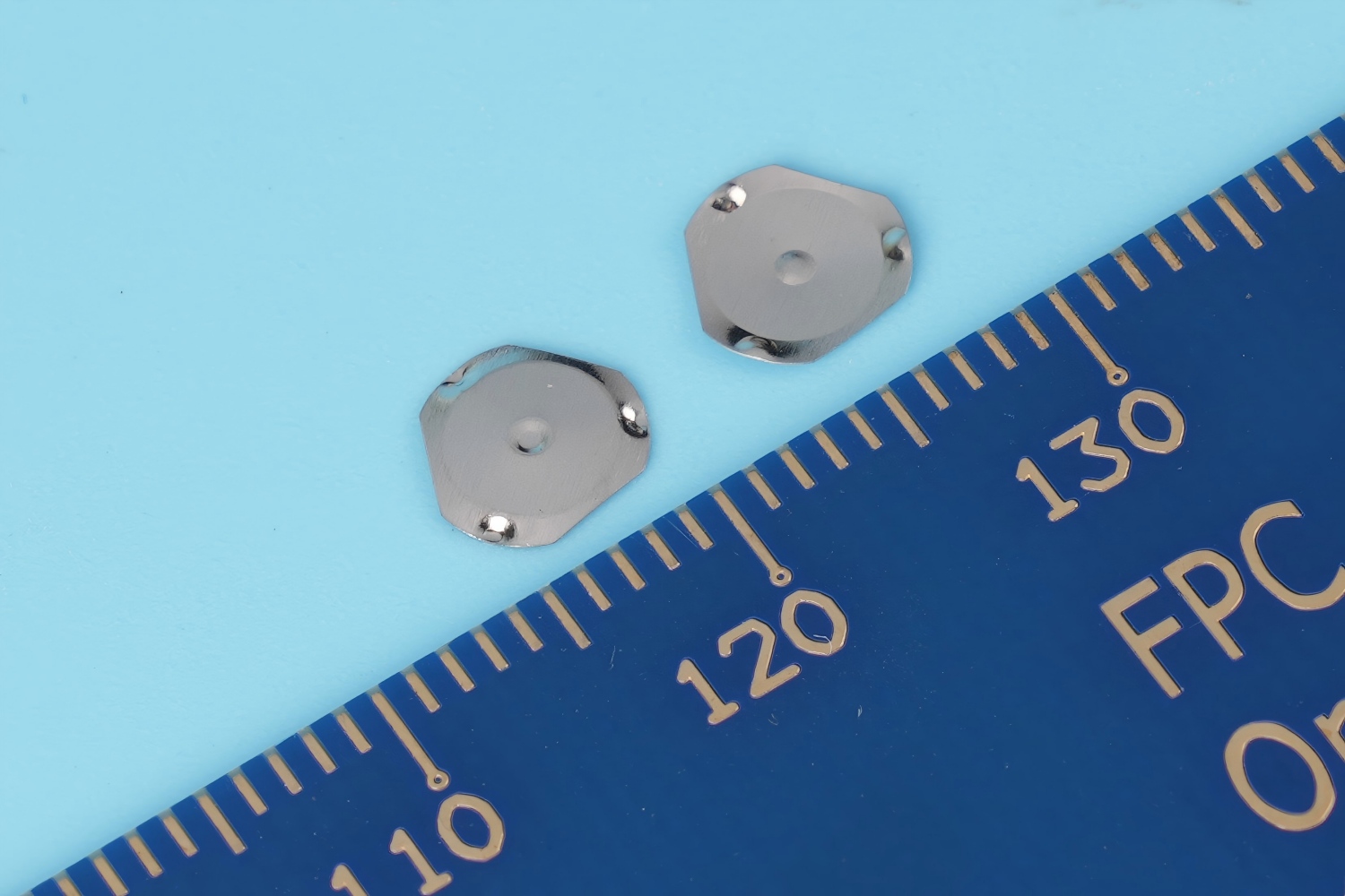
Pitch and spacing define how domes are arranged within an array. These parameters directly affect keyboard layout, usability, and electrical performance. Standard keyboard designs often follow established pitch values, such as 19 mm for full-size keyboards. However, compact devices may require tighter spacing.
Key considerations for pitch and spacing include:
- Key size compatibility
The dome spacing must match the keycap dimensions. - Electrical isolation
Adequate spacing prevents unintended contact between adjacent circuits. - Manufacturing tolerance
Proper spacing allows for slight variations without affecting performance. - User ergonomics
The layout should support comfortable typing and accurate key targeting.
In custom designs, pitch can be adjusted to meet specific requirements, such as wearable devices or industrial control panels. EBest Circuit (Best Technology) supports high-precision array design with contact accuracy within ±0.05 mm, ensuring reliable performance even in compact layouts.
Can metal dome arrays achieve mechanical-keyboard-like tactile response?
Mechanical keyboards are known for their distinct tactile feedback and satisfying key press feel. While metal dome arrays operate differently, they can be engineered to deliver a similar experience. The tactile response of a metal dome depends on its force curve, snap ratio, and material properties. By optimizing these factors, designers can create a sharp and noticeable feedback similar to mechanical switches.
Comparison between metal dome arrays and mechanical switches:
| Feature | Metal Dome Array | Mechanical Switch |
|---|---|---|
| Structure | Thin and flexible | Individual switch modules |
| Tactile feedback | Adjustable | Fixed by switch type |
| Thickness | Ultra-thin | Relatively thick |
| Cost | Lower | Higher |
| Customization | High | Moderate |
Although the feel is not identical, metal dome arrays offer a strong tactile response while maintaining a slim profile. This makes them ideal for devices where space is limited but tactile quality is still important. With proper design, users can enjoy a responsive and satisfying typing experience without the bulk of mechanical switches.
How to reduce click noise while using metal dome arrays in keyboards?
Noise control is an important factor in many applications, especially in office environments and consumer electronics. While metal domes naturally produce a clicking sound, several methods can reduce noise without compromising tactile feedback.
Effective noise reduction strategies include:
- Using lower snap ratio domes
This reduces the sharpness of the click sound. - Adding cushioning layers
Soft layers can absorb impact and reduce noise. - Optimizing key structure
Proper keycap design can minimize sound transmission. - Adjusting dome material thickness
Thinner domes often produce softer sounds. - Applying damping films
These films help absorb vibration during actuation.
The goal is to balance tactile feedback with acoustic performance. A well-designed system can provide a satisfying feel while keeping noise at a comfortable level. EBest Circuit (Best Technology) works closely with customers to fine-tune dome characteristics, ensuring that both tactile and acoustic requirements are met.

Conclusion:
Keyboard metal dome arrays offer a powerful combination of flexibility, performance, and efficiency. They enhance typing feel in membrane keyboards, provide extensive customization options, and support high-speed manufacturing processes.
EBest Circuit (Best Technology) continues to support global customers with advanced metal dome solutions, offering high precision, fast delivery, and strong technical support. If you are looking for a trusted partner for your keyboard metal dome array projects, feel free to reach out: Email: sales@metal-domes.com