Custom metal dome design guide decisions should be made as a system. Dome geometry, force curve, actuator, PCB contacts, spacer, venting and assembly tolerances all affect the final switch response. Specifying only diameter and trip force can produce a dome that looks correct on a drawing but feels weak, binds in the stack or makes intermittent contact after assembly.
This guide explains which parameters need to be controlled, when a standard dome is sufficient, and how to validate a custom tactile switch before tooling is frozen.

What Is a Custom Metal Dome Design?
A custom metal dome is a formed stainless-steel spring contact developed around a specific mechanical envelope, tactile target and PCB interface. Customization may change the diameter, outline, leg geometry, height, dimple, holes, trip force, return force, travel or surface finish. It does not automatically mean that every dimension should be unique.
The practical objective is repeatable switch behavior after the dome is installed. A useful specification therefore defines the complete force-displacement response and the surrounding stack, not just the loose dome. EBest Circuit(Best Technology) can develop a custom metal dome from a drawing, a sample or a defined mechanical and electrical target.
When Does a Metal Dome Need a Custom Design?
Use a standard dome when its footprint, force range and travel fit the product without forcing changes to the PCB or enclosure. Custom development is justified when at least one requirement cannot be met by a released standard part:
- The available PCB area requires a non-standard diameter, outline or leg orientation.
- The actuator and overlay stack needs a force curve or travel that standard parts cannot deliver.
- The contact pattern, trace routing or keep-out area requires a special dome geometry.
- The product needs a dimple, hole, plated surface or environmental treatment not available in the standard series.
- Installed performance must stay inside a narrow force, height or contact-resistance window.
Customization adds tooling, sampling and validation work. It is unnecessary when a standard dome meets the installed requirements; creating a unique drawing without a functional reason increases replacement and second-source risk.
How Do Size and Shape Affect Metal Dome Performance?
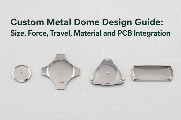
Shape selection starts with the available footprint, actuator location and PCB routing. The same nominal force does not make two shapes interchangeable because their support points, collapse behavior and contact geometry differ.
| Shape | Design Advantage | Main Constraint | Typical Selection Logic |
|---|---|---|---|
| Round | Symmetrical response and simple placement | The outer contact and routing must fit around the circumference | General-purpose key with a centered actuator |
| Four-leg | Legs create routing space and defined support points | Leg orientation must match the pad and assembly | Dense PCB layout or a larger tactile key |
| Triangle | Compact three-point support | More sensitive to orientation and actuator centering | Restricted footprint with controlled alignment |
| Oblong | Fits elongated keys or narrow housings | Off-axis loading must be checked carefully | Non-square user interface or rectangular key cap |
| Custom outline | Can clear components or match an unusual contact pattern | Highest tooling and validation burden | Use only when standard geometry cannot fit the interface |
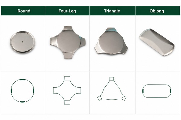
Size also changes stiffness, travel and the space needed for the PCB contacts. As published selection ranges, the circle metal dome series covers 3-20 mm with typical forces of 100-600 gf, while the four-leg metal dome series covers 5-20 mm with typical forces of 125-500 gf. These are series ranges, not a guarantee that every size is available at every force; the exact combination must be checked against the drawing.
How Should Force, Travel and Click Ratio Be Specified?
A complete tactile target should define trip force, return force, travel and the measurement method. Trip force is the peak load immediately before snap-through. Return force is measured as the dome recovers. Travel is the displacement between the defined rest and actuation points. Click ratio describes the force drop that creates tactile contrast:
Click ratio = (trip force – return force) / trip force x 100%
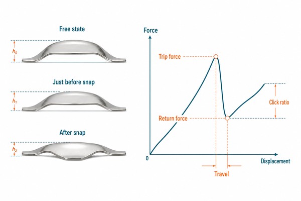
A higher click ratio usually feels more distinct, but it does not by itself guarantee a better key. A stiff overlay, off-center actuator or trapped air can reduce the perceived snap even when the loose-dome curve is acceptable. State whether force is measured on the loose dome or in the final stack, define actuator tip geometry and speed, and use the same fixture for prototype approval and production checks.
Do not specify trip force alone. Two domes can share the same peak force yet differ substantially in return force, travel and hysteresis. For a key that must recover quickly, return force is especially important; for a shallow enclosure, total installed travel may be the limiting parameter.
Which Material and Plating Should You Choose?
Stainless spring steel is the normal base material because it combines elastic recovery, fatigue resistance and corrosion resistance. Material grade and thickness are part of the forming process and should not be changed independently after the force curve has been approved.
| Surface Option | Why It Is Used | Design Boundary |
|---|---|---|
| Bare stainless steel | General tactile contact in a controlled environment | PCB finish, cleanliness and contact resistance still require validation |
| Nickel plating | Additional surface protection or compatibility with a specified contact system | Plating changes surface behavior and must be included in life testing |
| Silver plating | Low-contact-resistance interface for selected applications | Tarnish exposure and mating finish must be considered |
| Gold plating | Stable contact surface for demanding low-level signals or corrosive conditions | Higher cost; use only where the electrical or environmental requirement supports it |
Choose the surface as a contact system with the PCB finish, expected current, contamination risk and operating environment. A plated dome should be tested against the actual pad finish and assembly process. Cosmetic appearance alone is not a sufficient reason to add plating.
How Should a Metal Dome Be Integrated with PCB Contact Pads?
The PCB normally uses an electrically isolated center pad and outer contact. In the released state, the dome rests on the outer contact without connecting the center. When the actuator collapses the dome, its center touches the center pad and closes the circuit. The pad must follow the selected dome drawing; a generic circular footprint should not be reused for every shape.
Control these PCB details before fabrication:
- Keep the center pad electrically isolated from the outer ring or leg contacts.
- Match support points and clearances to the actual dome outline and tolerance.
- Keep solder mask, silkscreen, vias and raised features out of the dome movement area unless the approved drawing allows them.
- Specify a flat, clean contact finish and avoid residue that can increase contact resistance.
- Keep the actuator axis aligned with the dome center and define lateral assembly tolerance.
- Provide a vent path so displaced air does not slow or cushion dome movement.
For geometry examples and layout checks, use the dedicated PCB contact pad design guide together with the released dome drawing. Prototype testing should use production-intent PCB finish, solder mask and adhesive construction.
How Do Actuator, Overlay, Spacer and Venting Affect Tactile Feel?
The user feels the complete stack, not the bare dome. Actuator diameter, tip radius, alignment and stiffness determine where the load enters the dome. A tip that is too small can create local stress; a wide or off-center actuator can interfere with collapse and recovery. The actuator must remain centered across housing and PCB tolerances.
The overlay and spacer control preload, clearance and air movement. Excess preload can reduce travel or hold the dome near collapse. Too much clearance can create lost motion before the user reaches the dome. Adhesive squeeze-out or a blocked vent can create inconsistent sound and force between keys. Review metal dome actuator types and metal dome venting as parts of the same stack-up decision.
A useful tolerance analysis includes the dome free height, spacer thickness, adhesive thickness, overlay deflection, actuator height, PCB flatness and housing position. Test the minimum and maximum stack conditions, not only nominal parts.
When Should You Use Loose Domes or a Custom Dome Array?
Loose domes suit low key counts, mechanically captured installations and designs where the housing positively locates each dome. They minimize carrier material but require a reliable placement and retention method.
A single-key array or multi-key array fixes domes to a PET carrier with an adhesive spacer. This improves orientation, placement speed, vent routing and retention. A custom dome array is usually the better choice when a keypad has multiple switches, tight positional tolerances or automated assembly requirements. CAD, PDF, Gerber, PCB, CAM or a dimensioned sketch can define the layout, but the final array drawing should also show vent paths, alignment features, tail construction if present and adhesive keep-outs.
For loose domes used in automated placement, tape-and-reel packaging can protect orientation and support controlled feeding. Packaging format should therefore be selected together with the assembly method rather than after the dome geometry is released.
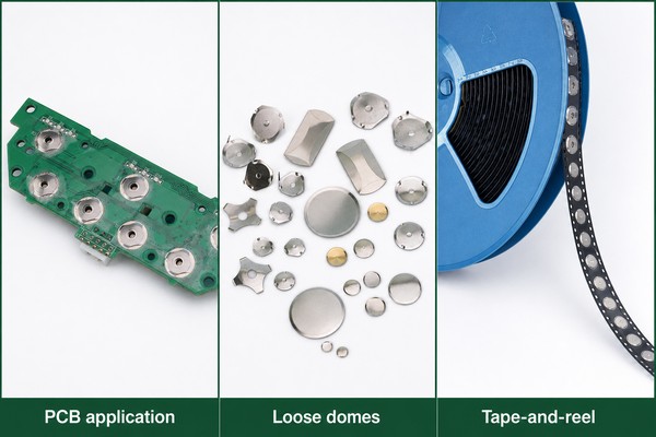
| Assembly Format | Best Fit | Main Validation Point |
|---|---|---|
| Loose dome | Few keys with positive mechanical capture | Placement, orientation and retention |
| Single-key array | Individual adhesive-backed switch locations | Adhesive window and vent path |
| Multi-key custom array | Keypads and repeatable production placement | Cumulative pitch, alignment and stack tolerances |
Which Tolerances and Prototype Tests Matter?
The drawing should control only dimensions that affect fit, force, contact or assembly. Over-tightening cosmetic or non-functional dimensions raises tooling and inspection burden without improving switch performance.
Prototype validation should include:
- Dimensional and visual inspection for diameter, height, legs, dimples, burrs and plating condition.
- Force-displacement testing for trip force, return force, travel and click ratio using a defined fixture.
- Electrical testing for closed resistance, contact stability and bounce under the intended signal conditions.
- Repeated cycling at the production-intent actuator position and speed.
- Environmental exposure appropriate to the application, followed by force and electrical rechecks.
- Installed assembly testing at minimum, nominal and maximum stack conditions.
Do not approve the dome from loose-part data alone. A prototype can pass force testing on a flat fixture and still fail in the product because of PCB bow, spacer compression, actuator offset or restricted venting. Freeze the acceptance method with the prototype so production inspection measures the same characteristics.
What Design Inputs Should Be Frozen Before Tooling?
Tooling should start only after the functional interfaces are stable. Freeze the following design inputs in one controlled drawing set:
| Input | What Must Be Defined |
|---|---|
| Dome geometry | Shape, diameter or envelope, free height, legs, holes, dimples and orientation |
| Tactile response | Trip force, return force, travel, click ratio and measurement conditions |
| Contact system | Base material, plating, PCB pad geometry, surface finish and electrical test limits |
| Mechanical stack | Actuator geometry, overlay, spacer, adhesive, preload, clearances and vent path |
| Assembly format | Loose dome, single-key array or multi-key array; alignment and retention method |
| Reliability | Cycle target, environment, test sequence and pass/fail limits |
| Source files | Dimensioned drawing plus PCB/Gerber/CAD data with revision control |
EBest Circuit(Best Technology) engineering review is most effective when the dome drawing, PCB contacts and actuator stack are evaluated together. Conflicting revisions are a common source of prototype delay, so every released file should carry the same revision identifier.
What Custom Metal Dome Design Mistakes Should You Avoid?
- Specifying only diameter and trip force while leaving return force, travel and test method undefined.
- Selecting a custom shape before checking whether a standard round or four-leg dome fits.
- Reusing a generic PCB footprint without matching the selected dome’s support and contact geometry.
- Allowing the actuator to load an edge or leg instead of the dome center.
- Omitting vent paths or blocking them with adhesive, overlay printing or enclosure features.
- Ignoring cumulative stack tolerance and validating only nominal components.
- Changing material, plating or thickness after approving the tactile curve.
- Approving loose-dome samples without testing the production-intent PCB, spacer and actuator.
The correction is to treat the dome, PCB and mechanical stack as one controlled switch assembly. Each custom feature should solve a documented fit, tactile, electrical or reliability requirement.
FAQ
What specifications define a custom metal dome?
At minimum, define shape, size, free height, trip force, return force, travel, click ratio, material or plating, PCB contact geometry, actuator conditions and life-test requirements. Add leg, dimple, hole and array details only when the design needs them.
Is trip force the same as tactile feel?
No. Trip force is one point on the force-displacement curve. Perceived feel also depends on force drop, return force, travel, actuator geometry, overlay stiffness, preload and venting.
What click ratio should a metal dome have?
There is no universal value for every interface. Select a range that provides clear feedback without compromising return force or fatigue life, then validate it in the installed stack using the intended actuator.
Can a standard metal dome be modified without new tooling?
Some changes, such as choosing an available force or plating option, may fit an existing series. Changes to outline, diameter, leg geometry, free height or formed features generally require engineering review and may require dedicated tooling.
Does a metal dome require a PCB vent?
The cavity needs a controlled air path. Without venting, trapped air can cushion collapse, slow return or make different keys feel inconsistent. The vent may be implemented in the spacer, adhesive or PCB layout, depending on the stack.
What files are useful for a custom dome array?
A dimensioned PDF plus CAD, Gerber, PCB or CAM data is useful. Include dome centers, orientation, contact pads, alignment holes, outline, adhesive windows, vent paths and revision information.
Should the prototype be tested as a loose dome or in the product?
Both tests are useful, but installed testing is required for release. Loose-dome data isolates the spring component; assembly testing reveals preload, alignment, venting, PCB flatness and tolerance effects.
What causes inconsistent key feel across a keypad?
Common causes include actuator offset, spacer-thickness variation, blocked vents, adhesive intrusion, PCB bow, overlay variation and mixed dome orientation. A force map across the assembled keypad helps separate local stack issues from dome-lot variation.
Conclusion
A reliable custom dome starts with the complete switch interface: geometry, force curve, material, PCB pads, actuator, spacer, venting and tolerance stack. Use a standard part where it meets the installed requirement; customize only the parameters tied to fit, tactile response, electrical contact or reliability. Then approve the result with production-intent stack testing.
For feedback on a drawing or prototype configuration, review this custom metal dome design guide with your mechanical and PCB files, then contact EBest Circuit(Best Technology) at sales@metal-domes.com or through the Metal-Domes contact page.