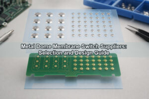
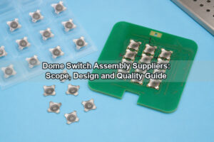
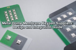
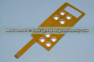
A flexible membrane switch combines a thin user-interface overlay, pressure-sensitive adhesives, a flexible circuit and a switching element in one laminated assembly. When metal dome arrays provide the tactile action, the design must coordinate dome geometry, circuit pads, spacer openings, vent paths, key actuators and the enclosure support. Treating these parts as one stack-up produces more consistent force, contact and alignment than selecting each layer independently.
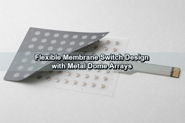
The same construction can be adapted for compact instruments, industrial control panels, medical interfaces, vehicle controls and sealed equipment. The engineering choices change with circuit density, bending requirements, lighting, key spacing and the required tactile response.
What Is a Membrane Switch?
A membrane switch is a momentary electrical switch in which at least one contact is formed on, or attached to, a flexible substrate. A typical assembly uses printed polyester film, an etched flexible circuit or a thin PCB beneath a graphic overlay. Pressing a key closes an open circuit; releasing it restores the open state.
The word “membrane” describes the flexible construction, not one fixed contact technology. A non-tactile design may use two printed circuit layers separated by a spacer. A tactile design may use embossed polyester, polydomes or stainless-steel snap domes. Metal domes add a defined snap point and return force while also serving as the movable conductor.
How Does a Flexible Membrane Switch Work?
In the released state, the center contact and outer contact remain electrically separate. The metal dome rests on the outer contact area above the center pad. Force from a finger, rubber key, molded plunger or overlay emboss transfers to the dome crown. At the snap point, the dome collapses and its center touches the center pad, completing the circuit.
The controller detects this temporary closure through the circuit tail. When force is removed, the dome returns to its original curvature and opens the contact. The assembled feel is not determined by dome force alone. Overlay stiffness, actuator diameter, adhesive thickness, venting and housing support all change the force transmitted to the dome.
What Layers Form a Flexible Membrane Switch Stack-Up?
A metal-dome membrane switch commonly contains seven functional groups. Some designs combine layers, while backlit or shielded versions add optical and conductive films. The drawing should specify material, thickness and adhesive boundary for every layer rather than showing only the overall thickness.
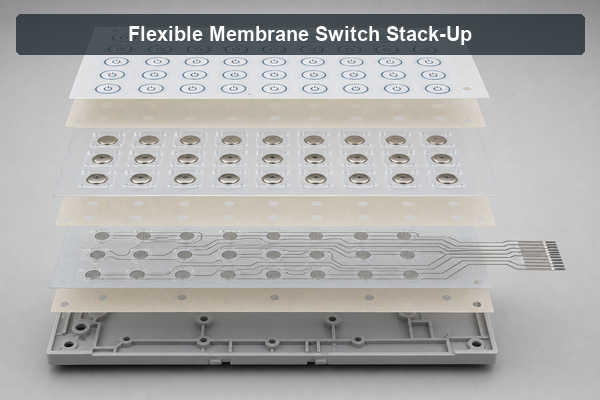
| Layer | Main Function | Design Control |
|---|---|---|
| Graphic overlay | Legends, key surface and environmental barrier | PET or polycarbonate, texture, windows and embossing |
| Overlay adhesive | Bonds the overlay to the switch body | Cutouts, bond width and compatibility with ink |
| Dome retainer | Locates each metal dome | PET thickness, carrier pocket and registration |
| Spacer and vent layer | Provides dome clearance and airflow | Cavity diameter, channel width and sealing route |
| Circuit layer | Routes the switch matrix and tail | Printed PET, FPC or PCB; pad finish and resistance |
| Rear adhesive | Mounts the assembly to the enclosure | Housing material, surface energy and flatness |
| Backer or housing | Supports the switch during actuation | Rigidity, local bosses, openings and assembly tolerance |
Layer count alone does not indicate quality. A thinner construction can still perform reliably when dome height, spacer clearance and support flatness are controlled. Conversely, adding layers without checking adhesive compression may increase force variation or misalign the actuator.
Should the Circuit Layer Use Printed PET or an FPC?
Printed PET is suitable for many low-current switch matrices because it is thin, economical and easy to integrate with a flat tail. Silver ink forms the traces, while carbon ink may protect exposed contact or connector areas. Trace length, width and curing control the circuit resistance, so long narrow routes require closer review.
An etched copper FPC is preferable when the layout needs finer routing, lower conductor resistance, component attachment, repeated flexing or a compact reinforced connector. Polyimide also tolerates higher processing temperatures than printed PET. It usually costs more, and the copper stack may require strain relief where the tail bends.
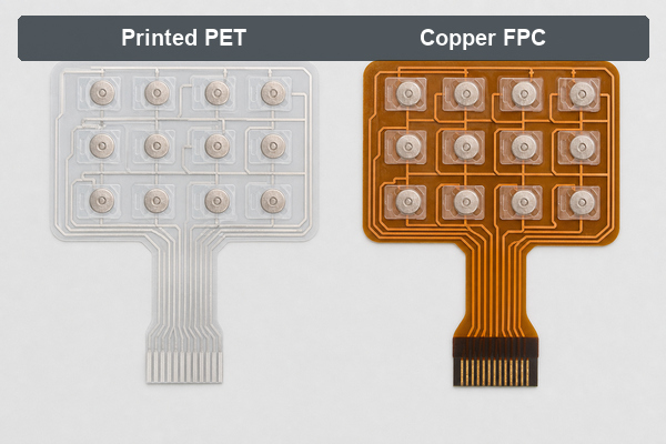
| Decision Point | Printed PET | Copper FPC |
|---|---|---|
| Typical conductor | Screen-printed silver and carbon inks | Etched copper on polyimide |
| Routing density | Moderate | Fine traces and compact spacing |
| Electrical resistance | Higher; depends strongly on printed geometry | Lower and more predictable |
| Component integration | Limited, commonly LEDs with conductive adhesive | Better suited to LEDs and small SMT components |
| Repeated flexing | Suitable for static or limited bending | Better when bend radius and copper direction are designed correctly |
| Cost and tooling | Usually lower for simple key matrices | Higher but justified by density or electrical requirements |
The contact pad geometry must match the selected dome in either construction. Changing from PET to FPC does not correct an undersized center pad, insufficient dome support or poor alignment between the carrier and circuit.
How Do Metal Dome Arrays Create Tactile Feedback?
A metal dome array holds multiple snap domes on a registered PET or adhesive carrier. The array keeps dome position, orientation and spacing stable during assembly. It can be supplied as a single-layer carrier for a simple PCB or FPC installation, or as a multi-layer structure with spacer and adhesive features.
Dome diameter, shape, height, force and click ratio establish the basic tactile response. The final response also depends on the actuator contact area. A small hard plunger concentrates force and may overstress the dome crown. A wide or off-center actuator can delay snap action and produce uneven key feel. The actuator should press close to the dome center while remaining within the recommended contact region.
For dense keypads, array registration is as important as individual dome tolerance. Tooling holes, optical marks or housing features should reference the same datum system used for the circuit pads and graphic overlay. This reduces cumulative offset across a large keypad.
How Should Adhesive, Spacer and Vent Channels Be Designed?
The spacer opening must give the dome enough room to collapse and recover without rubbing its edge. Adhesive should retain the dome and seal the assembly without flowing into the active cavity. A narrow bond land may lift during repeated operation, while an oversized bond area can restrict dome movement.
Air inside the dome cavity must move when the key is pressed and released. A vent channel cut into the spacer provides this path. The channel should avoid the electrical contact area and retain enough adhesive width for bonding. Shared vent networks can save space in a large array, but their route and cross-section should remain balanced so one key does not feel slower than another.
A sealed keypad does not always require a completely trapped cavity. Internal venting can connect dome cavities to a protected area within the assembly. The design should be evaluated with the overlay and housing installed because lamination pressure, adhesive flow and enclosure compression can narrow a channel that appears adequate in the die-cut drawing. See the detailed metal dome venting guide for the airflow principles.
When Is LGF Needed for a Backlit Membrane Switch?
Light guide film is useful when a backlit membrane switch needs thin, distributed illumination across several keys or legends. Side-emitting LEDs inject light into the film. Printed or laser-formed extraction features redirect light upward through selected areas of the graphic overlay.
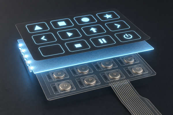
LGF is more suitable than placing one top-firing LED under every legend when product thickness, light uniformity or power distribution matters. The design must still control LED position, film coupling, extraction density, opaque masking and light leakage between adjacent keys. Large illuminated areas may need more than one LED input or a graded extraction pattern.
The optical layer must not interfere with dome travel or venting. A custom LGF dome array should therefore be reviewed as an optical and mechanical stack rather than added after the keypad geometry is fixed.
How Are Keypad Switches Assembled with Overlays and Actuators?
Keypad switches may be actuated directly through an embossed graphic overlay, through a silicone rubber key, or through a molded plastic plunger. Direct overlay actuation keeps the assembly thin, but overlay stiffness and emboss geometry become part of the force path. Rubber keys provide sealing and travel but must have stable bosses above the dome centers. Plungers provide precise force transfer when their diameter, height and guide clearance are controlled.
Assembly normally proceeds from registered circuit and dome-array layers to spacer, optical layers, overlay adhesive and graphic overlay. The final laminate is then mounted to a flat backer or enclosure. Registration features should remain accessible long enough to align the critical layers before they are removed or covered.
- Keep the actuator center within the dome’s approved press zone.
- Prevent adhesive edges from contacting the moving dome.
- Support the circuit directly beneath each active key.
- Maintain clearance around display windows, LEDs and enclosure bosses.
- Apply lamination pressure uniformly to avoid local thickness changes.
Which Tail and Connector Options Fit Flexible Membrane Keypads?
The circuit tail can terminate in exposed printed contacts, a reinforced FFC/FPC end, crimp contacts or a board-mounted connector. Printed PET tails commonly use carbon-coated contacts and a stiffener selected for the mating connector thickness. Copper FPC tails may use plated fingers and a polyimide stiffener.
Tail exit position should avoid active keys and tight enclosure edges. A tail that folds immediately at the laminate boundary can concentrate stress and peel the rear adhesive. Provide a controlled bend radius and, where necessary, a tail filler or strain-relief feature at the exit. Connector pitch, contact side, stiffener thickness and insertion direction must match the receiving board before the tail artwork is released.
How Do You Control Alignment, Thickness and Actuation Force?
Alignment control begins with a common datum scheme across the overlay, dome carrier, circuit and housing. If each supplier dimensioned from a different edge, tolerances can accumulate until the plunger no longer presses the dome center. Registration holes, camera marks and hard tooling datums reduce this risk.
Thickness should be tracked by functional zone, not only as one overall number. The active key stack includes overlay, adhesive, dome height, spacer and circuit. The tail zone may omit several layers, while a display window or LED zone may add clear spacers. Local thickness changes can tilt the assembly or alter housing compression.
Actuation-force verification should compare the loose dome curve with the completed keypad curve. A custom dome array can hold dome force tightly, but an undersized plunger, stiff overlay or restricted vent path can still shift the assembled result. Measure representative keys at the center and edges of the panel.
What Reliability Tests Matter for Flexible Membrane Switches?
Reliability testing should use the finished stack-up and the intended support condition. A loose dome life test confirms the metal component, but it does not expose overlay wear, adhesive movement, vent restriction, connector fretting or circuit-trace cracking.
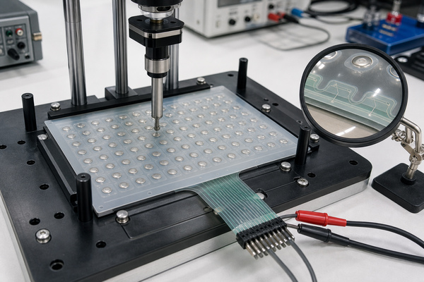
- Force-displacement and click-ratio measurement on assembled keys.
- Contact resistance and insulation resistance before and after cycling.
- Repeated actuation at representative speed, load and temperature.
- Tail bend, connector insertion and strain-relief testing.
- Adhesion and dimensional checks after heat, humidity or chemical exposure.
- Backlight brightness, uniformity, color and light-leakage inspection.
- Visual registration checks for overlay, actuator, dome and circuit pad centers.
Test limits should match the product environment. An indoor instrument may prioritize tactile consistency and legend wear, while a vehicle or industrial panel may also require temperature cycling, vibration, cleaning-fluid resistance and controlled sealing.
What Are Membrane Switches Used For?
Membrane switches are used where a low-profile, customizable and cleanable interface is preferable to an array of separate mechanical switches. Common examples include medical instruments, laboratory equipment, industrial controllers, access panels, appliances, vehicle controls, handheld devices and test equipment.
Metal dome arrays are particularly useful when the operator needs a clear snap response through a thin overlay. LGF can add uniform backlighting, while FPC construction supports dense routing or integrated LEDs. A rigid PCB-based switch may be more appropriate when the panel must carry many components or withstand high local assembly loads.
Frequently Asked Questions About Flexible Membrane Switches
What Does a Membrane Switch Look Like?
From the outside, it usually looks like a printed flat control panel with outlined or embossed keys and a flexible tail. Internally, it contains laminated films, adhesives, circuit contacts and optional metal domes, LEDs, shielding or LGF.
Can You Replace Membrane Switches?
A membrane switch can be replaced when the enclosure permits removal, the rear adhesive can be released without damaging the surface, and the connector remains accessible. Fully bonded or molded assemblies are harder to service. Replacement parts must match the tail pinout, contact side, outline, key locations and thickness.
Can a Flexible Membrane Switch Be Waterproof?
It can be designed for water and dust resistance by using a continuous perimeter seal, compatible overlay and rear adhesives, protected tail exits and sealed windows. The required protection must be validated on the complete enclosure because mounting surfaces, cable exits and housing joints are part of the seal.
What Is the Difference Between a Dome Array and a Membrane Switch?
A dome array is the tactile switching layer that positions metal domes on a carrier. A membrane switch is the complete interface assembly, which may include the dome array together with the graphic overlay, circuit, adhesives, backlighting and mounting layers.
Conclusion
A reliable flexible membrane switch begins with a coordinated stack-up. Circuit technology, dome geometry, adhesive clearance, venting, actuator alignment, tail design and backlighting should be evaluated together before the layer drawings are finalized.
EBest Circuit(Best Technology) supports custom metal dome arrays for PET circuits, FPC circuits, PCB interfaces, LGF backlighting and keypad assemblies. For a design review or custom array discussion, contact sales@metal-domes.com.