
An inverted metal dome switch is a fault when a normally open dome remains collapsed after the actuator is released instead of springing back. The key may lose its click, remain electrically closed or produce an unreliable return. First remove external pressure and check the released electrical state; then inspect the dome and its support. A stuck input alone does not prove the metal dome is permanently inverted: enclosure preload, adhesive interference and a PCB short can look similar.
What Is an Inverted Metal Dome Switch?
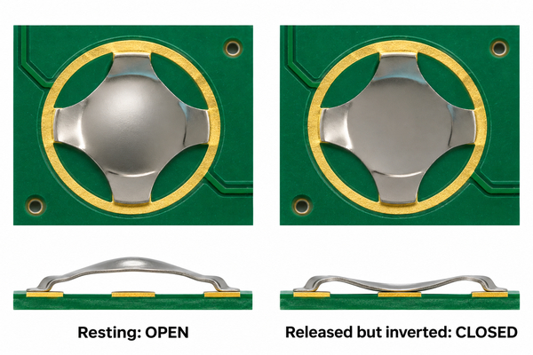
A conventional momentary metal dome rests with its center raised above the circuit’s center pad. Pressing it causes a snap-through and contact closure; releasing the force allows the spring geometry to lift the center and reopen the circuit. In this article, metal dome inversion refers to the unwanted condition in which that return does not occur. The physical part may remain dished downward, or it may return too weakly to restore the specified open state.
Do not infer inversion from the word “collapsed” during a normal press. Snap-through is how a working switch operates. The diagnostic distinction is the state after the load is removed. An intentionally bistable dome is a different specified design; its two stable positions are not a failure merely because it stays in one state. Check the approved part drawing and switch function before labeling a dome defective.
When Is Dome Inversion a Fault Rather Than Normal Snap Action?
For a normally open momentary switch, a fault exists when the released dome no longer recovers its designed profile or the contact remains closed without external force. Compare a suspect key with an unused part of the same approved construction under equal support. A visually shallow dome is not automatically failed; height, travel and release behavior are part-specific.
Observe both mechanical and electrical return. If the key lacks a release click but the circuit opens, investigate reduced return force and actuator interference. If the circuit remains closed but the dome appears to return, investigate a board-level short, moisture or an unintended conductive bridge before replacing the spring. One symptom is not a root-cause verdict.
What Makes a Metal Dome Stay Collapsed?
Excess travel can push the center below the dome’s intended working plane and damage its transition ring, the formed region that helps the spring return. A dented ring, bent leg or repeated off-center load can also reduce the return force. For most conventional designs, pushing past the plane of the supported feet is a warning; some specially designed domes permit over-travel, so the drawing for the actual part takes precedence.
A collapsed metal dome may instead be held down by the stack around it: an actuator that rests on the dome, excess adhesive, a shifted carrier, an incorrectly sized spacer or a housing rib. In that case the spring may recover when the load is removed. Record the as-found stack before separation, because opening the housing can release the preload and erase the evidence.
Contact geometry also matters. A raised center pad, a board area that flexes under the key, or legs that do not sit evenly can create local over-travel even when the nominal enclosure travel seems acceptable. Verify the real pad height and support condition, not just the free dome shape on a desk.
How Can an Actuator Cause Permanent Dome Inversion?
An actuator should apply force near the dome center without crushing the transition ring. A wide flat plunger, a sharp point, a roller sweeping over the dome or a misaligned key can load the hinge region rather than the intended center. A hard travel stop must work with the complete housing, overlay, carrier and PCB stack; a stop dimension on the drawing alone does not prove that the assembled key cannot over-travel.
As one manufacturer-specific screening reference, Snaptron recommends a flat-bottom actuator no wider than 25% of its dome diameter. Applied to an 8 mm example, that is 0.25 x 8 mm = 2 mm. This is Snaptron’s published recommendation, not a universal limit or a measured specification for our domes. For any selected part, compare its own actuator guidance and use a measured assembled travel/force test to decide whether the plunger and stop are acceptable.
If several adjacent keys fail after enclosure assembly but loose domes recover normally, measure the actual actuator-to-dome gap at the installed stack height. Replacing every dome before correcting a common housing preload will reproduce the failure. Preserve one failed assembly and one passing assembly for a like-for-like sectioning or measurement.
Can Uneven Support or PCB Pad Geometry Cause Inversion?
Yes. The feet or perimeter need the support intended by that dome design. If one leg sits on adhesive, solder mask buildup or an uneven surface, the transition ring can twist during actuation. The same nominal force can then produce a different local bend at one edge. Check the installed key’s flatness, pad positions and interference around the transition ring under magnification.
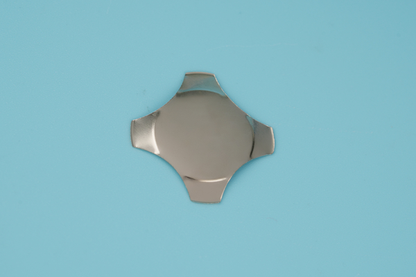
A four-leg metal dome places its four feet on the circuit in a pattern different from a round C-series dome. That distinction changes what must be supported and where the center pad belongs. Our C-series page describes an over-travel-capable series, but that statement must not be transferred to a four-leg part or every C-series variant without checking the actual drawing, mating pad and assembled test.
How Do You Confirm a Metal Dome Is Stuck Closed?
Reproduce the symptom with no finger on the key and record the released voltage at the controller input, using the actual circuit diagram and a suitable high-impedance measurement. Then check whether the signal changes when the external actuator or enclosure is removed under an approved diagnostic procedure. A continuity beeper on an unpowered board may identify a short, but its thresholds do not tell you how the complete input behaves in service.
For a clearly labeled hypothetical example, consider a 3.3 V input with a 10 kOhm pull-up and a normally open dome to ground. A passing released key reads about 3.3 V; a suspect key reads 0.05 V with no force, then returns to 3.3 V after its housing actuator is lifted. Under those stated conditions, the change supports assembly preload or mechanical interference, not proof of a permanently damaged dome. If the 0.05 V remains after the actuator is removed, isolate the dome/contact path from a possible PCB short. The actual controller thresholds and release limits come from the product’s approved design, not these illustrative values.
Repeat the measurement across enough press/release cycles to reproduce the reported fault and note the exact key position, orientation, supply and enclosure state. If removing a carrier or dome would disturb evidence, photograph it first. A one-time open reading after disassembly does not establish the cause of an earlier stuck-closed event.
| Released-state observation | Controlled next check | What the result can support |
|---|---|---|
| Input stays low only while housing is fitted | Measure installed actuator gap and stack height | Preload/interference is plausible; verify the assembly |
| Input stays low with actuator lifted | Inspect dome profile, then isolate contact from PCB trace | Possible inverted dome or electrical short; not yet separated |
| Dome is visibly down and has weak/no return | Compare same part on correct flat support and inspect transition ring | Spring damage is plausible; preserve sample |
| Dome springs back but input remains low | Check conductor bridge, residue and circuit path | Do not classify by electrical symptom alone |
How Do You Separate a Damaged Dome from Enclosure Preload?
Start with the complete failing assembly and document the key’s released electrical state and tactile response. Remove one source of load at a time: first the external keycap or housing, then any overlay component that can be removed without disturbing the dome. If the key returns after the housing is lifted, investigate the installed gap, spacer stack and actuator stop before blaming the metal.
If the dome remains inverted on a level, correctly supported circuit after the external load is removed, inspect the transition ring and legs against a known-good sample. A replacement that works in the same enclosure for one press is insufficient: repeated assembly cycles may cause the same over-travel. Conversely, if a verified good dome also stays closed at the same PCB position, review pad geometry, board flex and electrical shorts.
Keep part swaps traceable. Label the original dome, board position and any replacement, and do not re-form the suspect part by hand before the as-found profile is recorded. Manual reshaping changes the evidence and cannot restore a documented fatigue life or force curve.
What Should a Force-Travel Test Show After Release?
A force-travel test should capture both the downward trip and upward release branches with the dome supported as it is in the actual design. Record the actuator tip, alignment, travel reference, speed, contact measurement and number of cycles. A healthy momentary switch should return to its specified open geometry and electrical state when the load goes back to zero; the exact trip force, release force and travel must be compared with the approved part drawing or qualified sample.
A curve with an absent or diminished return branch, a zero-load closed contact or a profile that stays depressed points to a recovery problem, but the test fixture can cause it if the legs are unsupported or the plunger over-travels. Run the same method on a passing part, and photograph both before and after the test. A bench curve without fixture and support conditions is not a reliable acceptance result.
| Measurement | Condition to record | Decision use |
|---|---|---|
| Released contact voltage or resistance | Actual supply/load or meter method; actuator fully unloaded | Verify open-state requirement from approved circuit specification |
| Trip and release force | Part number, support, plunger and test speed | Compare both branches with qualified part limits |
| Free height and travel | Datum at supported feet/perimeter before and after cycling | Check permanent set and over-travel evidence |
| Repeat cycles | Specified count, force method and assembled stack | Verify fault does not recur after correction |
Can a Collapsed Metal Dome Be Repaired?
A permanently deformed or bistable dome should be replaced rather than bent back for a production repair. Hand reshaping may restore a temporary click while changing the transition ring, trip/release forces and fatigue behavior. Replace with the specified geometry and force grade, then inspect the mating contact and support. If the new dome fails in the same location, the original component was probably not the only problem.
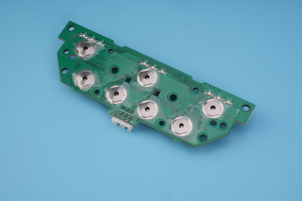
For a retained array, the dome may not be independently replaceable without disturbing the adhesive carrier or vent path. Follow the approved rework procedure or replace the relevant assembly. The release decision must be based on the finished key’s specified return, contact state and repeat test, not simply on a restored tactile click.
How Can You Prevent Metal Dome Inversion During Assembly?
Support every foot or perimeter region on the intended flat surface before any actuation. Do not test a loose dome between fingers or press its center below an unsupported edge. Use placement tools that avoid denting the transition ring, and keep wide rollers or rigid flats from loading the entire spring region. These precautions address the same damage mechanism described in our handling guidance.
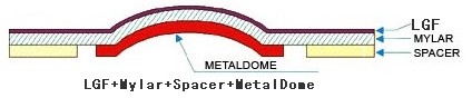
Validate the complete stack at its tolerance extremes: PCB finish and flatness, adhesive/carrier thickness, spacer opening, actuator length and housing stop. A metal dome array positions domes on a carrier but does not by itself prevent preload or over-travel after installation. Check the opening, vent route and pad registration with the finished enclosure, not only the free-standing sheet.
For an assembly that has already produced a stuck-closed key, quarantine the affected lot until the failure is separated into dome damage, stack interference or circuit short. Document the corrective change and repeat the electrical and tactile tests under the original failing condition. Also watch for any new weak-click or intermittent-open failures introduced by a revised actuator or spacer.
What Should You Specify for a Replacement Dome or Array?
Provide the original part number or drawing, dome outline, diameter, free height, trip and release forces, travel, finish, PCB pad pattern and the complete actuator/spacer stack. State whether the observed failure was a dome that stayed physically down, a contact that stayed electrically closed, or both. These are different clues and may lead to different corrective actions.
At EBest Circuit(Best Technology), we can review a round dome, four-leg dome or carrier array against the supplied drawing and failure record. We cannot promise an inversion-free result from the shape alone; the installed support, travel stop and finished-switch test determine suitability. Send the as-found photos, circuit layout and test conditions to sales@metal-domes.com for an engineering review.
Inverted Metal Dome Switch FAQs
Does a metal dome invert every time it is pressed?
A working dome snaps through during actuation and returns when released. The fault is a normally open dome that remains down or cannot restore its specified released state.
Does a stuck-closed input always mean the dome is collapsed?
No. Enclosure preload or an electrical short can hold the input low. Check the circuit with the actuator unloaded, then isolate the dome and PCB path before replacing parts.
When investigating an inverted metal dome switch, preserve the original failed geometry before changing the stack. A valid corrective action must restore both the specified release behavior and the open electrical state under the assembled operating conditions.