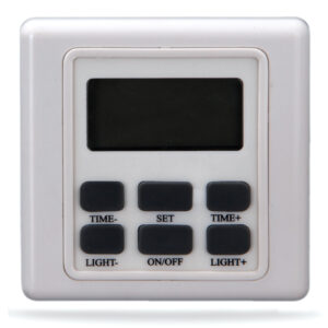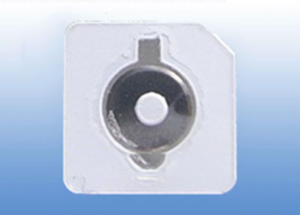

A metal dome placement machine presents one thin snap dome, locates a switch contact on a PCB, flex circuit or membrane, and releases the dome in the required orientation. A working line depends on the dome, its package, the feeder, the pickup head and the supported circuit as one matched system. A fast machine cannot compensate for a package it cannot index or a dome it cannot release reliably.

What Does a Metal Dome Placement Machine Do?
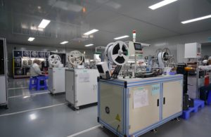
The machine replaces repeated hand placement with a controlled sequence: present a dome, take or dispense a single piece, locate the target, place it, and advance to the next key. Some dedicated systems dispense from a cartridge directly onto the circuit; other lines use a pick-and-place head and a carrier-tape feeder. These are different machine architectures, not interchangeable names for the same tool.
The output is a correctly positioned switch element, not a solder joint. Our tape-and-reel metal dome page specifically notes that normal loose snap domes do not become solderable merely because they can run through SMT-style placement equipment. The drawing must state how the placed dome is retained, for example by the specified carrier or subsequent switch construction.
How Does Automated Metal Dome Placement Work?
In automated metal dome placement, the operator loads the approved package and fixture, selects the matching job and confirms the first pickup. The feeder advances one pocket or cartridge position. The head takes one dome, checks or preserves its orientation, moves to the programmed switch coordinate and releases it onto the prepared circuit. The cycle then repeats. A camera or sensor can inspect the pickup or placed part, but the inspection method must be shown to detect the actual errors expected on that line.
At the end of a panel, the machine may unload the circuit or wait for an operator. The line still needs a defined reaction to an empty pocket, a missed pickup, an unplaced dome and an interrupted run. Without that logic, a cycle counter can look complete while one switch position remains empty.
Which Metal Dome Feeder Fits the Package?
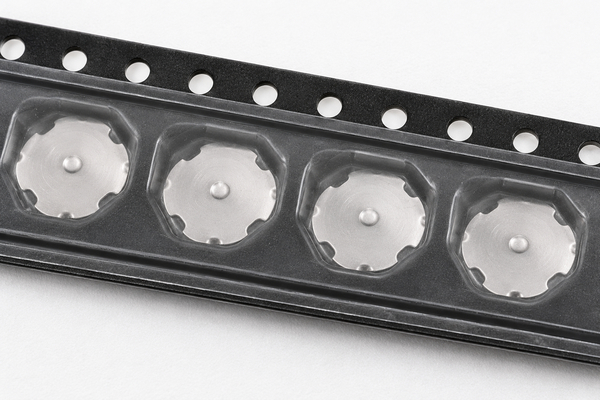
A metal dome feeder is the interface between supplied parts and the placement head. Our site documents domes supplied in plastic tubes, individual carrier-tape pockets and adhesive arrays. A tube-compatible dispenser advances a guided sequence of parts to a release point; a reel feeder indexes pockets by pitch and exposes the pickup face; an array presents several domes on a single adhesive carrier. The feeder must match the approved dome geometry and package revision, not just the nominal diameter.
| Supply format | Presentation to equipment | Critical interface check |
|---|---|---|
| Tube | Guided line of domes dispensed at one end | Tube profile, exit, dome orientation and single-part release |
| Tape-and-reel | One intended dome per indexed pocket | Tape width, pocket pitch, pickup face and peel path |
| Adhesive dome array | Multiple pre-positioned domes on one carrier | Carrier datum, liner removal, key registration and adhesive bond |
Our tube-packed domes and reel-packed domes are supply options for different assembly routes. A machine builder’s feeder specification and a trial with the actual packaged sample determine compatibility. The package type alone does not guarantee drop-in operation on every placement machine.
Tube Dispenser vs Reel Pick-and-Place: What Changes?
A tube dispenser can carry a guided supply of compatible domes and release them one by one. A reel-fed pick-and-place route advances sealed pockets and lifts exposed domes with a head. That changes the consumable, feeder tooling, refill method and single-part detection point. It does not make one approach universally faster: panel size, key count, travel, replenishment and rejection rates govern the useful output.
For example, Snaptron’s SureShot illustrates a cartridge-fed architecture. For that route, confirm the cartridge dimensions, exit geometry and placement program with the equipment maker using the actual dome sample. We can supply the specified dome and package for that compatibility trial.
How Does Metal Dome Pick and Place Handle the Part?
During metal dome pick and place, the head must lift or dispense a shallow spring element without permanently flattening it, changing its orientation or carrying a second piece. A vacuum nozzle needs a compatible contact area and suction setting; a mechanical dispenser needs a controlled single-part exit. Release is as important as pickup: a dome held on the nozzle at the next move can create both a missing switch and an unintended extra part.
For our four-leg domes, the leg orientation and the contact pattern belong in the approved drawing. The correct head approach and placement force depend on that particular dome and substrate. Check the part after repeated cycles for bent legs, crown damage and altered actuation; a successful one-time lift is not enough.
What Coordinates and Board Support Does the Machine Need?
The placement program needs a datum, each key’s X/Y position, the intended rotation and the circuit revision. Locate those coordinates from the board or fixture drawing, not from a screenshot. The fixture must hold the PCB or flex flat enough that the target remains where the head expects it. On a flexible circuit, unsupported local movement can shift the effective position even when the programmed coordinates are correct.
Before the production run, place a small first-article set and inspect the dome edge against the actual contact geometry. An optical fiducial can correct board translation or rotation if the machine supports it, but it cannot fix a wrong key ID or an outdated panel drawing. For arrays, the carrier outline and tooling datum replace repeated single-dome coordinates with a whole-pattern alignment task.
How Are Placement Accuracy and Orientation Checked?
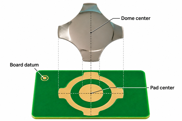
Measure the placed dome against the switch-pad datum or another controlled feature. The inspection should distinguish a centered dome from one shifted far enough to alter support or contact. Record both X and Y offset, plus rotation where legs or noncircular shapes make it relevant. A camera’s advertised pixel size is not the same as demonstrated placement accuracy after feeding, pickup, board fixturing and release.
Look at the face and leg direction, not just the outer silhouette. Confirm the inspection can reject a reversed dome, a missing dome and a double pickup using prepared challenge samples. Electrical and tactile checks on the assembled switch then confirm that the positioned part operates in its final stack; visual centering alone cannot prove actuation or reliable contact.
What Can Fail Between Pickup and Release?
Common process observations include an empty pocket, a dome that stays in the package, a dome that follows the head after the release command, a reversed piece, a misplaced piece, or damage from the head. A nested pair can also be picked when loose domes are not separated. Each mode needs a different detection point; one final count cannot identify them all.
If two pieces arrive together, our separate anti-stacking metal domes discussion covers that specific part and packaging problem. For machine qualification, the practical question is whether the line detects the pair before it is hidden under a carrier or overlay and whether the reject is traceable to a particular key position.
How Should You Measure Useful Placement Throughput?
Separate a machine’s advertised maximum placement rate from accepted switches per hour on the actual job. For a panel with multiple keys, include feeder reloads, panel handling, vision checks, rejects and changeovers. Record the same start and stop boundaries when comparing two methods. A machine that cycles quickly but needs frequent intervention may deliver fewer accepted panels than a slower, better-matched process.
For a simple trial, count accepted placed domes after inspection, divide by elapsed run time, then report the panel count, domes per panel and rejects separately. For example, if 100 panels each contain 8 keys and 10 placements are rejected, the trial produced 790 accepted placements; without the elapsed time and rework result, no hourly throughput can be stated. This is an illustrative count, not a measured result for our factory or any machine model.
What Should a Placement Trial Record?
Run the approved dome and package through first-article setup, steady operation, a refill and a stop/restart. Inspect the same key IDs before and after interruptions. Keep the package revision and machine setup with the results so a later change in pocket geometry, nozzle or fixture can be evaluated against the original run.
| Trial stage | Observation | Evidence to retain |
|---|---|---|
| Feeder index | Correct part presented at every requested position | Package revision, empty-pocket and jam counts |
| Pickup and transfer | One undamaged dome in the intended orientation | Missed/double pickup and orientation rejects |
| Placement | Dome centered on the specified contact geometry | Measured offsets by key and first-article images |
| Refill and restart | Part count and key sequence remain synchronized | Interruption log and post-restart inspection |
| Assembled switch | Specified tactile and electrical response | Test method, limits and recorded results |
The acceptance limits and trial size belong to the actual switch specification. A machine supplier’s nominal accuracy may be a useful screening value, but it cannot replace the measured distribution on the customer’s dome, circuit and fixture.
When Is a Dome Array Better Than Single-Dome Placement?
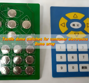
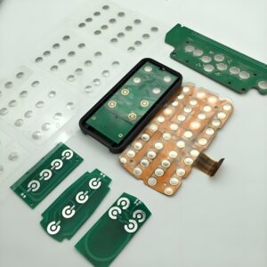
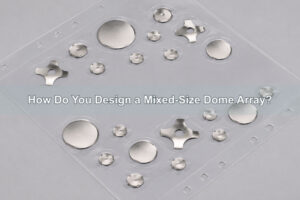
If many switch positions share one circuit and can be registered together, a custom dome array places specified domes on an adhesive carrier before final application. That can remove repeated loose-part pickup at each key. It changes the control problem to carrier alignment, liner removal, adhesive condition and verification of every key under the sheet.
An array is not automatically the better choice for every prototype or mixed-size job. A single-key dome array can be useful for a smaller trial or individual placement, while a reel may fit a repeated automated process. Compare the actual circuit geometry, order volume, change frequency and assembled-switch test rather than assuming a package wins on speed alone.
What Can We Supply for Your Placement Line?
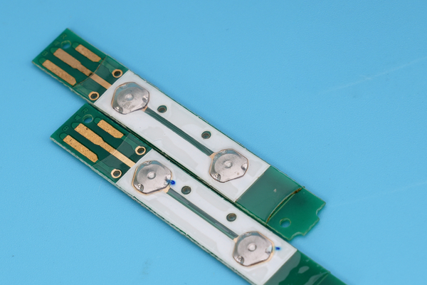
At EBest Circuit(Best Technology), we manufacture metal domes and dome arrays and offer bulk, tube, tape-and-reel and peel-and-place supply formats described on our product pages. We can review the dome drawing, switch-pad layout, pickup face, package orientation and expected quantity with your machine or assembly team. The selected equipment and the completed line trial determine the achievable placement accuracy and rate for that dome-and-circuit combination.
To assess the dome/package combination, we need the dome part or required shape and force, circuit drawing with key coordinates, desired packaging, target volume and any feeder or head specification already selected. If the machine has not been selected, the sample should still be tested with the intended feeder and placement process before the package is frozen.
Metal Dome Placement Machine FAQs
Can every SMT pick-and-place machine place loose metal domes?
No. The feeder, pickup head and program must handle the exact dome and package. Tape-and-reel presentation can make a standard placement route possible, but the setup still needs a real pickup and release trial.
Does automatic placement mean the metal dome should be soldered?
No. Placement and joining are separate decisions. Our standard reel-packed metal dome page specifically states that normal metal domes are not intended for soldering merely because the packaging suits an SMT machine.
What should I send before specifying a metal dome feeder?
Provide the actual dome drawing or sample, target circuit and key coordinates, intended package, required orientation, planned quantity and the equipment maker’s feeder interface. These inputs are needed to test compatibility with a metal dome placement machine, not to assume it from a generic equipment name.
Send us these drawings and package requirements for a dome sample and quotation. We can review the part and supply format for your proposed feeder; final machine compatibility still needs a placement trial on the intended line.