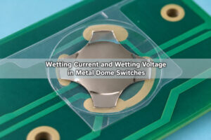

Switch tease occurs when a tactile snap gives the impression that a switch has operated, but additional movement or force is still needed to achieve electrical closure. In a metal dome assembly, a click before electrical contact can leave a light press unregistered even though the key feels responsive. The mechanical snap and the electrical switching event must therefore be measured together.
What Is Switch Tease?
Switch tease is the mismatch between tactile feedback and electrical operation. The user feels the dome snap, relaxes finger pressure, and expects an input; the contact may not yet have reached the resistance required by the circuit. Pressing farther can then make the key work.
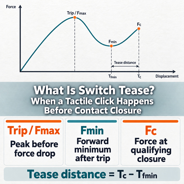
For the closing stroke, the force-displacement definition measures tease distance from the forward-stroke force minimum, Fmin, to the electrical closure position, Tc. This is more specific than the entire travel from the trip peak to closure. The opening stroke has its own switching behavior and should not be substituted for the closing measurement.
Tactile switch tease describes a mechanical/electrical relationship, not a diagnosis of one defective part. A bare dome, its carrier, PCB contacts, actuator and enclosure can all influence the final key response. A good snap by itself does not demonstrate a reliable circuit connection.
Why Can the Tactile Click Occur Before Electrical Closure?
The click comes from a mechanical change in the dome’s shape. Electrical closure depends on a conductive path between the dome and the intended PCB contacts. Those events need not occur at the same actuator position.
Additional motion may be needed to bring the moving contact onto the pad or to develop a sufficiently conductive interface. Surface contamination can also leave high resistance after physical contact begins. These are different mechanisms: correcting mechanical clearance will not necessarily correct a contaminated contact surface.
In a complete keypad, some actuator travel also goes into compressing the overlay or moving an inadequately supported PCB. The finger can feel a distinct snap while the intended contact-loading condition has not been reached. The useful question is whether the input becomes valid during the user’s normal press, not whether the dome can eventually be forced closed.
How Is Contact Closure Force Shown on a Force-Displacement Curve?
Contact closure force, Fc, is the applied force at the position where the defined electrical closure criterion is met. It must be located using an electrical measurement, not inferred from the peak or lowest point of a mechanical curve.
| Mark | Meaning on the closing stroke | What to record |
|---|---|---|
| Trip / Fmax | Peak force before the forward force drop | Applied force and corresponding travel |
| Fmin | Forward-stroke minimum after the trip peak | Force and its position, Tfmin |
| Fc | Applied force when the closure criterion is reached | Force plus the resistance criterion |
| Tc | Actuator position at that closure event | Travel using the same reference as Tfmin |
| Tease distance | Tc minus Tfmin | Distance units, not force units |
A force displacement curve contact closure measurement needs synchronized force, displacement and electrical records. For the delayed-closure case illustrated above, the bracket spans Tfmin to Tc. The vertical difference Fc minus Fmin is a force difference; it is not the tease distance. Fmin is also not the minimum force on the return branch.
If the electrical event occurs during the force drop or before the forward minimum, keep the actual event order in the results. Do not move the closure marker simply to make the measurement look like an example diagram. Check the stated test definition before interpreting such a trace.
What Does Tactile Switch Contact Force Tell You?
Tactile switch contact force needs a clear definition in a drawing or test report. The actuator force recorded at electrical closure is not automatically the local normal force at each microscopic contact point. Force is transmitted through a deforming dome and, in an assembled key, through other layers as well.
Two keys with similar trip force can therefore have different electrical closure positions. Likewise, increasing trip force alone does not establish that closure will occur earlier. Compare Fc, Tc and the contact-resistance behavior along the same closing stroke rather than choosing a dome by its peak force alone.
We manufacture custom metal domes with drawing-defined shape, size, trip force and travel. For a tease investigation, include the required electrical event and the assembled actuator geometry alongside those mechanical requirements. That gives the dome selection a specific operating target without assuming that a force rating proves contact performance.
Is Switch Tease the Same as Contact Bounce?
No. Tease concerns the relationship between the tactile event and electrical closure. Contact bounce consists of repeated electrical transitions around making or breaking contact. One key can exhibit both, so the first transition and subsequent transitions should be retained in the recording.
| Observation | Likely distinction | Useful next measurement |
|---|---|---|
| Tactile snap, then continued open circuit during further travel | Delayed closure / possible tease | Locate Fmin and the first qualifying closure |
| Contact closes, opens and closes again during actuation | Contact bounce | Record the raw electrical waveform versus time |
| Contact remains closed, but the controller responds later | Scanning or debounce delay | Compare raw input with firmware recognition |
| Key never closes within permitted travel | Missing contact or another fault, not proven tease | Check contact path, alignment and travel limit |
Software debounce cannot make an open contact conduct. It can only qualify the electrical signal it receives. Keep the raw signal available when evaluating button debounce and switch bounce; otherwise a firmware delay can be mistaken for additional mechanical travel.
What Causes Excessive Tease in a Metal Dome Assembly?
Start with the interface between the dome and its intended contact pad. Wrong positioning, unsuitable contact geometry or a layer interfering with dome motion can change when closure occurs. A visibly centered dome is not sufficient evidence if its actuator presses off-center or the carrier shifts during assembly.
Then check the load path. Overlay stiffness, spacer opening, adhesive placement and actuator geometry affect how force reaches the dome. A restrictive layer can spread the load instead of concentrating it on the intended actuation region. Changing one layer may alter both feel and electrical response, so compare complete assemblies rather than only loose domes.
Finally, separate movement-related delay from electrical-interface problems. Debris, residue or deteriorated contact surfaces can produce unstable resistance even when the dome reaches the pad. Inspect and measure before increasing force: a harder press can temporarily conceal an interface problem without resolving its cause.
How Do Actuator Alignment, Preload and PCB Support Change Tease?
Alignment: locate the actuator relative to the dome and pad, not just the exterior keycap. An offset load can deform the dome asymmetrically. Check the tolerance stack between the enclosure, keypad, carrier and board, then test realistic off-center presses.
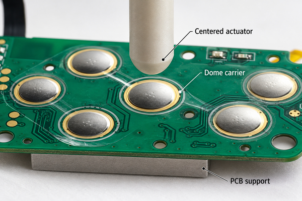
Preload: assembly compression can move the resting position along the force-travel response before the user presses the key. Excessive preload can reduce available movement or change tactile recovery. Zero-clearance and a defined preload are not interchangeable specifications; measure the assembled rest condition.
PCB support: board deflection consumes displacement measured at the actuator. Check whether the board moves relative to the fixture and whether the production enclosure supports it in the same way. Adding a laboratory support directly under the key may improve a test result while hiding a weakness in the actual housing.
Our plunger dome arrays provide an actuator feature above the carrier. Plunger diameter, height and alignment must match the keypad stack. An added plunger is a design option, not a universal cure for tease or permission to exceed the dome’s travel limit.
How Does the Resistance Threshold Change the Closure Point?
Electrical closure must have a stated resistance or circuit-level criterion. A continuity buzzer, an instrument with a specified resistance threshold and a digital input can declare closure at different points. Comparing their readings without recording the criterion can make unchanged hardware appear to have different tease.
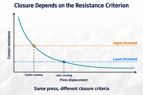
The diagram illustrates a monotonically decreasing resistance during a press. A stricter, lower resistance threshold is crossed later in this example. Real contacts may produce discontinuities or intermittent transitions, so retain those transitions instead of smoothing them away. Specify whether Tc means the first qualifying crossing and separately define the stability requirement after closure.
Record the test current, voltage limit, lead arrangement and measurement bandwidth. For low-resistance measurements, lead resistance can matter; a suitable four-wire method can separate lead contribution where the test arrangement permits it. A test signal that changes the contact condition must not be treated as equivalent to the product’s low-load circuit. Wetting current is a related electrical-interface issue, not a replacement for the mechanical closure measurement.
How Should You Test Mechanical Feel and Electrical Closure Together?
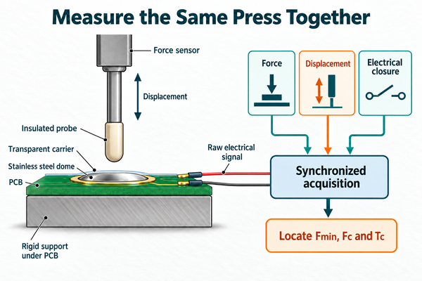
Use a controlled actuator, force sensor, displacement measurement and electrical acquisition on a shared time base. Test the completed carrier/PCB stack with representative support and preload. A finger press and a continuity beep are useful observations, but they cannot locate Fc and Tc precisely.
- Record the dome, pad finish, carrier stack, actuator geometry, support and resting preload. Define the electrical closure criterion before testing.
- Set a travel or force stop within the permitted component and assembly limits. Confirm fixture alignment and the displacement reference.
- Acquire force, travel and raw electrical response throughout the closing and return strokes. Record actuation speed, sampling rate and filtering.
- Identify the forward peak, Fmin and Tfmin. Locate the electrical event on the same record, then read Fc and Tc at that event.
- Calculate tease distance using the selected definition. Keep bounce, intermittent closure and final stable closure visible as separate observations.
- Repeat across keys, samples and relevant press locations. Compare the final enclosure with the development fixture before accepting a correction.
A small apparent interval can be comparable to measurement uncertainty. Check backlash, fixture compliance, sensor synchronization and displacement resolution before assigning a material or assembly cause. Environmental or life-cycle comparisons also need the same fixture and electrical criterion to be meaningful.
How Can You Diagnose a Click Without Reliable Contact?
| Symptom | Measurement or inspection | Design correction to evaluate |
|---|---|---|
| Tactile click but no electrical contact until a deeper press | Synchronized Fmin/Tc record and permitted remaining travel | Correct clearance or load transfer; verify the revised stroke |
| Center presses work, edge presses fail | Actuator offsets, dome position and keycap tilt | Improve location control or actuator contact geometry |
| Closure changes when the board is clamped | PCB movement relative to the housing | Match production support to the intended load path |
| Loose dome works but the completed keypad does not | Carrier, spacer, overlay and preload comparison | Remove interference and reassess the assembled stack |
| Closure position is unchanged but resistance is erratic | Contact surface inspection and raw resistance trace | Address residue, surface condition or contact compatibility |
| Raw input closes promptly but software responds late | Raw electrical signal versus controller event | Review scan/debounce settings without changing dome travel |
Treat these as investigation paths, not automatic diagnoses. Change one controlled factor, repeat the original test and confirm that the correction improves electrical operation without damaging return action or exceeding travel. If there is no qualifying closure at all, investigate an open circuit before assigning a tease value.
How Much Tease Is Acceptable in the Finished Keypad?
There is no single tease-distance limit that fits every dome, keypad stack and circuit. Acceptance must relate the closure event to available motion, allowable force and the expected user press. A key that works only when pressed against its hard stop may still fail in ordinary use even if it closes in a fixture.
Define the required event sequence and permitted variation across keys and samples. Include actuation location, electrical resistance criterion, stability after first closure, return behavior and the travel stop. Specify which environmental and endurance conditions apply to the product instead of transferring another keypad’s limits.
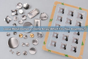
For our custom dome arrays, the drawing can define dome locations, cutouts, carrier outline and the selected dome types. Provide the actuator and support stack with these dimensions when closure timing matters. A dimensionally correct carrier and a good loose-dome click are necessary inputs to development, but the finished keypad still needs its mechanical and electrical events checked together.
FAQ
Can a switch click without making electrical contact?
Yes. The tactile snap is mechanical. Additional travel, insufficient contact loading or a poor conductive interface can leave the circuit open or above its allowed resistance after the click.
Does a higher trip force always reduce switch tease?
No. Trip force describes the mechanical peak, not where electrical closure occurs. Compare the complete force, displacement and electrical record before choosing a higher-force dome.
Can debounce software fix a tactile click but no electrical contact?
No. Firmware can reject unwanted transitions after a signal exists, but it cannot close a physical gap or restore a missing conductive path.
What information should accompany a tease investigation?
Provide the dome part, keypad stack, PCB pad drawing, actuator dimensions, support arrangement and synchronized measurements. Include the closure criterion and describe whether the failure appears during a light press, an edge press or only after assembly.
Need help matching a dome array to your keypad stack? Send your pad layout, actuator drawing, carrier dimensions and closure requirements to EBest Circuit(Best Technology) at sales@metal-domes.com. We can discuss the dome and array configuration against those inputs.