What Is a Tactile Push Button Switch?
Tactile push button switch is a compact electromechanical switch designed to give the user a clear physical response when pressed. That response is the familiar “click” or “snap” feeling under the fingertip. In many electronic products, this small component becomes the direct connection between the user and the circuit. It may control power, reset a device, change settings, select menu options, or confirm a command on a control panel.
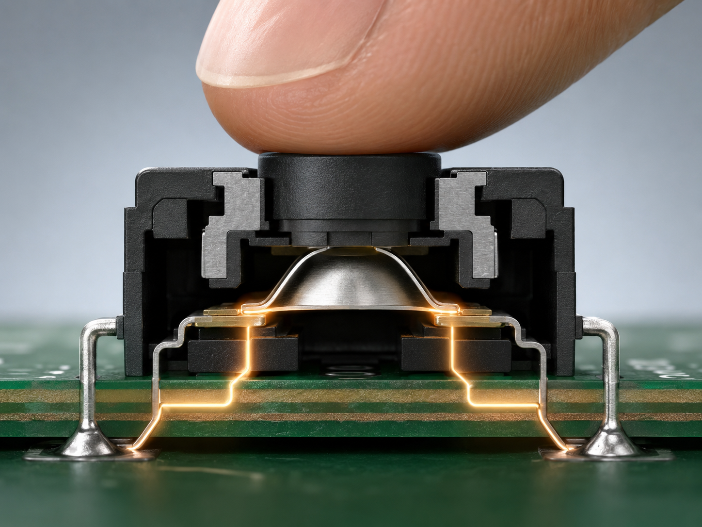
The word “tactile” is important because it describes the way the switch feels during operation. A tactile switch gives feedback through motion and force, not only through sound. When the button is pressed, the internal metal dome or spring contact changes shape, touches the circuit contacts, and creates an electrical connection. When the user releases the button, the dome returns to its original form and the circuit opens again. This makes the switch responsive, repeatable, and suitable for many electronic interfaces.
A push button tactile switch is widely used in consumer electronics, industrial control panels, automotive modules, handheld instruments, medical devices, smart home products, remote controls, test equipment, and communication devices. It can be mounted on a printed circuit board, integrated under a silicone keypad, placed behind a plastic actuator, or designed as part of a membrane switch structure. Because of this flexibility, engineers often select tactile switches when they need a dependable input device with a compact footprint.
How Does a Tactile Push Button Switch Work?
A tactile push button switch works by using mechanical pressure to change the electrical state of a circuit. In its normal condition, the switch is usually open. This means current does not pass through the switch contacts. When a user presses the actuator, the internal contact mechanism moves downward. Once the pressing force reaches a certain point, the metal dome or contact spring snaps into position and bridges the conductive pads. This closes the circuit and sends a signal to the PCB.
The “tactile” feeling comes from the snap action inside the switch. The switch does not move in a completely linear way. Instead, the force increases as the user presses down, then drops quickly when the dome collapses. That force drop is the click sensation. It tells the user that the input has been registered. This feedback is valuable because the user can press with confidence, even when the button travel is very short.
The working action can be summarized in a simple sequence:
- The switch is in the normal open state before pressing.
- The user presses the actuator or button cap.
- The internal metal dome or contact plate moves downward.
- The movable contact touches the fixed contacts.
- The circuit closes and the PCB receives the input signal.
- The user releases pressure.
- The dome springs back and the circuit opens again.
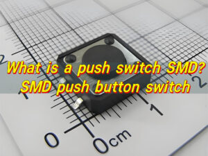
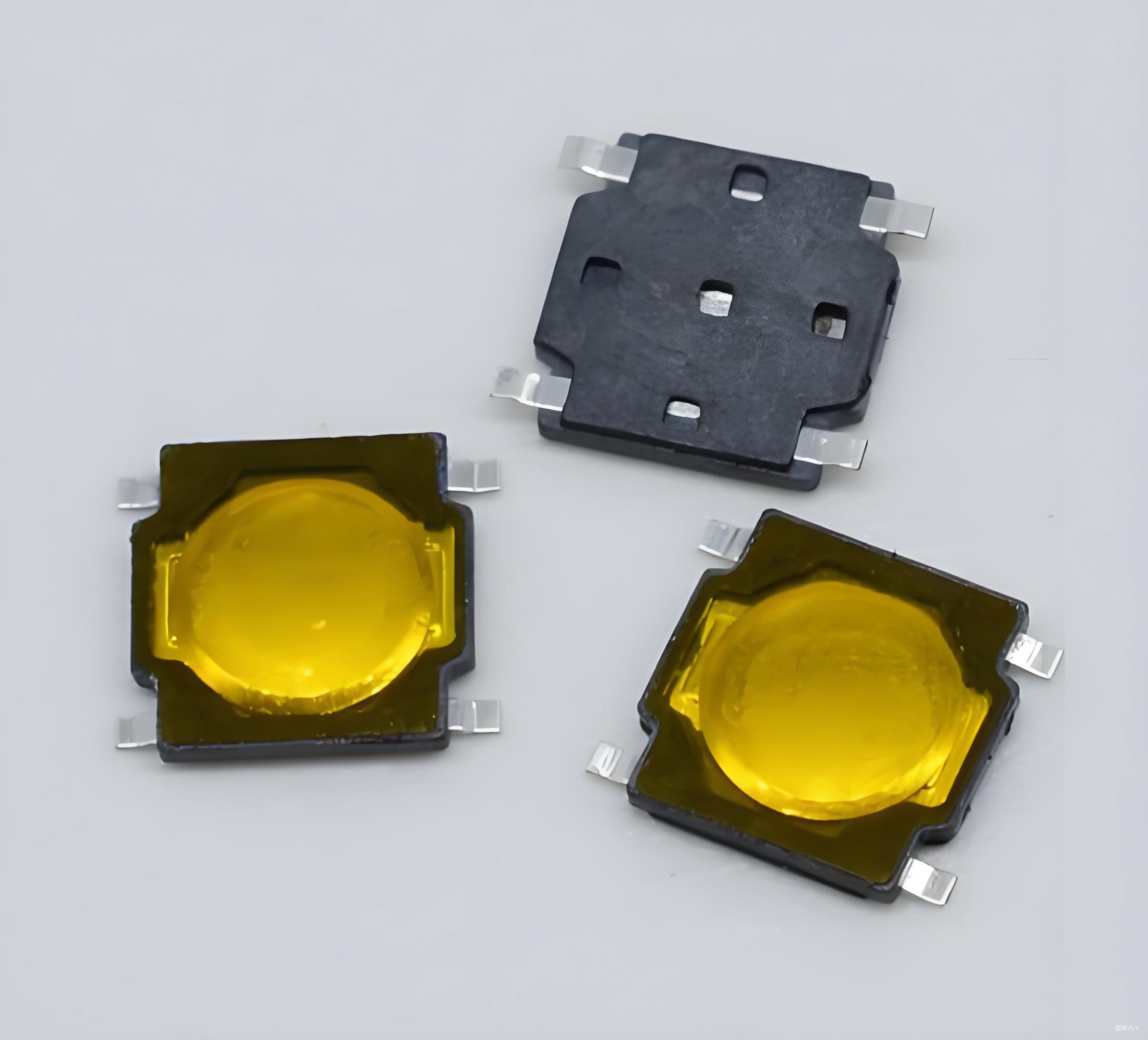
This working principle is used in both through hole and SMD tactile push button switch designs. Through hole models have pins that pass through the PCB, giving stronger mechanical retention. SMD tactile push button switch parts sit on the PCB surface and are soldered by reflow, making them suitable for automated SMT assembly and compact electronic products.
What Is a Momentary Tactile Push Button Switch?
A momentary tactile push button switch is a switch that changes its electrical state only while it is being pressed. Once the user releases the button, the switch automatically returns to its original state. This makes it ideal for signal input rather than continuous power control. For example, a reset button, menu key, volume button, pairing button, or mode selection button is often a momentary switch.
In many catalogs, this type may also be called a momentary tact tactile push button switch, momentary tactile tact push button switch, or simply a tact switch. These phrases usually describe the same basic function: the switch gives tactile feedback and remains active only during the pressing action.
Momentary operation is useful because many digital circuits only need a brief signal. A microcontroller can detect the press, perform a command, and then wait for the next input. This helps simplify product operation. For example, a user can press once to wake a device, press twice to change a mode, or hold the button to enter a setup state.
There are several common momentary switch configurations. The most typical is normally open, often written as “NO.” In this version, the circuit is open when the switch is released and closed when pressed. Some special designs can be normally closed, known as “NC,” but they are less common for standard PCB tactile applications. Most compact tactile switches used in electronics are normally open.
A momentary tactile push button switch is frequently selected for:
- Control panels, where users need clear click feedback.
- Handheld devices, where compact size and easy operation matter.
- Industrial electronics, where repeatable input is valuable.
- Medical instruments, where controlled user interaction improves confidence.
- Automotive modules, where space, height, and tactile force must align with the housing.
- Consumer products, where the feel of the button affects the product’s perceived quality.
The biggest advantage of a momentary tactile switch is its direct and familiar behavior. The user presses, feels the click, and the product responds. For engineers, this simple action still requires careful selection. Operating force, travel distance, height, soldering style, actuator shape, life cycle, and electrical rating all affect performance.
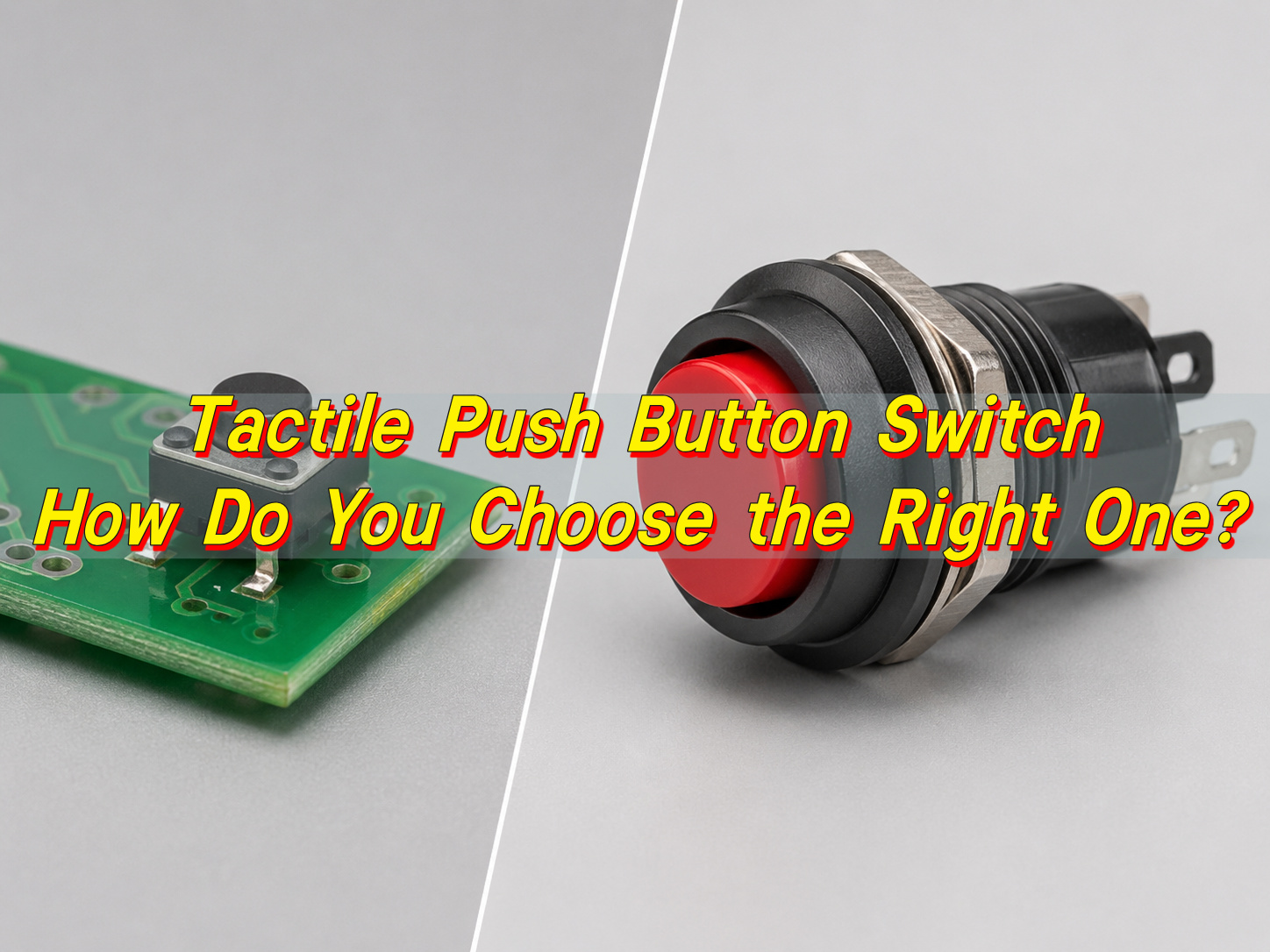
What Is the Difference Between a Tactile Switch and a Push Button?
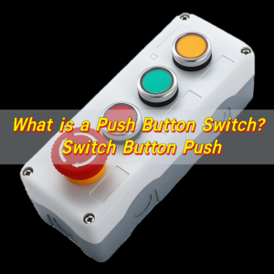
A tactile switch and a push button are closely related, but they are not always the same thing. A tactile switch is usually a small PCB mounted switch that provides a crisp click feel when pressed. A push button is a broader term. It can describe many button style switches, including tactile switches, latching switches, panel mount switches, illuminated switches, emergency stop buttons, and large mechanical control buttons.
In simple terms, every tactile switch can be considered a type of push button switch, but every push button is not necessarily a tactile switch. A large panel mounted push button may control mains power, lock into position, include an LED indicator, or use a long stroke mechanism. A small tactile switch, by comparison, is usually designed for low voltage signal input on a PCB.
| Comparison Item | Tactile Switch | Push Button |
|---|---|---|
| General Meaning | A compact switch with tactile feedback | A broad switch category operated by pressing |
| Typical Mounting | PCB mounted, SMD, or through hole | PCB mounted, panel mounted, chassis mounted, or cable connected |
| Feedback | Usually has a clear click feel | May be tactile, soft, latching, illuminated, or silent |
| Common Function | Momentary signal input | Signal input, power control, mode control, emergency control, or locking function |
| Size Range | Usually small and low profile | Can be very small or very large |
| Typical Application | Electronics, keypads, remote controls, control boards | Electronics, appliances, machines, panels, vehicles, and equipment |
| Circuit Type | Often normally open momentary | Can be momentary, latching, normally open, normally closed, or multi pole |
| Design Focus | Feel, height, footprint, actuation force, PCB assembly | Function, current rating, mounting style, durability, user interface |
A tactile switch vs push button comparison is really a comparison between a specific switch family and a wider category. When the application is a PCB mounted user input, the tactile switch is often the precise choice. When the application involves higher current, panel installation, locking function, or visible external control, another push button type may be more suitable.
In PCBA design, this difference also affects manufacturing. A tactile switch must match pad design, pick and place requirements, reflow profile, and enclosure clearance. A panel mounted push button may require wiring, connector planning, nut clearance, and mechanical fixation. EBest Circuit (Best Technology) often reviews this difference during DFM because a switch that fits electrically still needs to fit the assembly process and final product structure.
Push Button vs Tactile Switch: Which One Should You Use?
Choosing between a push button and a tactile switch depends on the function, mounting style, user experience, current rating, and product structure. The right choice should support both the circuit design and the way the user interacts with the product. A small wearable device, an industrial handheld controller, and a machine control cabinet may all use button input, but they call for different switch styles.
A tactile push button switch is usually the better choice when the circuit only needs a low voltage signal input. It works well with microcontrollers, compact PCB layouts, keypad structures, and consumer style control interfaces. The short travel and clear snap feeling allow fast response in a small space. It also supports automated PCB assembly when selected in SMD packaging.
A broader push button switch is often chosen when the button is mounted directly on a panel, carries higher current, includes illumination, requires a latching action, or needs a larger external actuator. These switches are common in machines, appliances, test systems, vehicles, and power control equipment. They may provide stronger mechanical presence and easier access for operators wearing gloves.
| Selection Factor | Choose a Tactile Push Button Switch When… | Choose Another Push Button Type When… |
|---|---|---|
| Mounting Method | The switch will be soldered directly to the PCB | The switch will be mounted on a panel or enclosure wall |
| Signal Type | The circuit needs a low current control signal | The switch handles higher current or direct power control |
| User Feedback | A crisp click feel is preferred | A larger travel, latching action, or illuminated button is preferred |
| Product Size | The product is compact or portable | The product has room for a larger mechanical control |
| Assembly Process | SMT or through hole PCBA assembly is planned | Cable connection, panel mounting, or manual installation is planned |
| Operation Style | Momentary input is required | Momentary, latching, key lock, or emergency stop function may be required |
| Cost and Volume | High volume automated assembly is important | Mechanical robustness or operator visibility is more important |
| Design Integration | The actuator is part of the enclosure or keypad | The button itself is the visible user interface |
For most electronic control boards, a tactile switch is the smart and efficient choice. It is small, responsive, economical, and easy to integrate into PCB assembly. For rugged equipment, outdoor panels, power units, or heavy duty operator interfaces, a larger push button can offer stronger mechanical handling and better visibility.
The decision also depends on how the button will be touched. A fingertip controlled consumer device may feel better with a light to medium operating force. A machine interface may need a firmer button to prevent accidental activation. A hidden reset switch may require a long stem or recessed access hole. A keypad under a plastic housing may need careful height matching between the switch actuator and the molded button.
What Does a Tactile Push Button Switch Diagram Show?
A tactile push button switch diagram shows how the switch connects mechanically and electrically to a circuit. It may include the internal contact structure, pin arrangement, PCB footprint, circuit symbol, operating direction, and recommended land pattern. For engineers, this diagram is more than a drawing. It helps confirm how the switch should be wired, mounted, and assembled.
The most common schematic symbol for a tactile switch shows a normally open contact. In the released state, the two contacts are separated. When pressed, the contacts close and connect the circuit. On a PCB layout drawing, the diagram may show four terminals. Although there are four legs, they often form two electrical nodes.
A diagram may also show the physical dimensions. These include body length, body width, actuator height, stem diameter, pin pitch, total height, and recommended PCB hole size or pad size. For an SMD tactile push button switch, the land pattern is especially important because solder pad geometry affects solder joint strength and placement accuracy. For through hole models, the hole diameter, pin spacing, and insertion direction should be reviewed carefully.
A complete switch diagram can help engineers understand several important details:
- Pin numbering, so the correct terminals are connected in the schematic.
- Circuit state, usually normally open for common tactile switches.
- Actuator direction, which confirms how the user presses the switch.
- Travel distance, showing how far the actuator moves.
- Operating height, which affects enclosure and keypad design.
- PCB footprint, allowing the switch to be soldered properly.
- Recommended soldering method, such as reflow, wave soldering, or manual soldering.
- Mechanical outline, which helps avoid collision with nearby parts.
For a tactile push button switch SMD part, the footprint should be handled with care during PCB design. Pads that are too small may reduce solder joint strength. Pads that are too large may create floating, skewing, or excess solder. The pick and place orientation should also be clear to the assembly team. A simple orientation mark in the PCB library can prevent confusion during production.
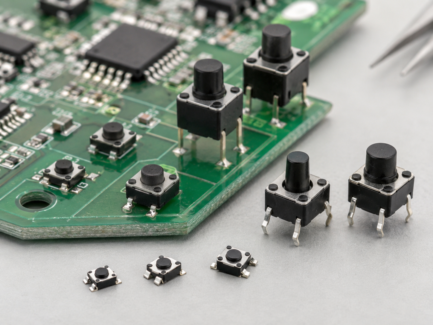
What Are Common Tactile Push Button Switch Sizes?
Tactile push button switches come in many sizes, heights, terminal styles, actuator shapes, and force ratings. The most familiar square body sizes include 3x3mm, 4x4mm, 6x6mm, 6.2×6.2mm, 7x7mm, 8x8mm, 10x10mm, and 12x12mm. There are also ultra small SMT versions for compact electronics and taller through hole versions for products with thicker enclosures.
The size of the switch is usually selected according to PCB space, actuator design, pressing comfort, and assembly method. A small 3x3mm switch can fit into portable products, earbuds cases, smart pens, and compact modules. A 6x6mm switch is one of the most widely used sizes because it offers a good balance between easy handling, stable pressing feel, and broad availability.
Height is just as important as length and width. The switch body may be 2.5mm high, 3.5mm high, 5mm high, 8mm high, 9.5mm high, or taller depending on the actuator design. A taller switch can reach through an enclosure opening or sit under a molded plastic key. A low profile switch is better for thin products and dense boards.
| Common Size | Typical Mounting Style | Typical Use Case | Design Notes |
|---|---|---|---|
| 3x3mm | SMD | Compact electronics, wearable modules, small control boards | Saves PCB space and supports light touch input |
| 4x4mm | SMD | Portable devices, small panels, compact consumer products | Good for medium density layouts |
| 6x6mm | Through hole or SMD | General electronics, control boards, appliances, instruments | Very common and widely available |
| 6x6x8mm | Through hole or SMD depending on type | Products requiring extra actuator height | Useful when the switch must reach a housing button |
| 7x7mm | SMD or through hole | Automotive, industrial panels, control modules | Provides a larger pressing surface |
| 8x8mm | Through hole or SMD | Larger buttons, handheld tools, interface panels | Offers more comfortable tactile operation |
| 12x12mm | Through hole or SMD | Larger control keys, button caps, equipment panels | Suitable for strong finger operation and visible buttons |
The operating force also varies by size and construction. Common options include 160gf, 180gf, 250gf, 260gf, 300gf, and higher force versions. A light force switch feels easy to press and is suitable for frequent user input.
When selecting a size, engineers should also consider sourcing stability. Standard sizes are often easier to purchase and replace across different suppliers. Special dimensions may be ideal for a unique product, but they should be checked for long term availability. For PCBA projects, EBest Circuit (Best Technology) can help review switch size together with PCB footprint, SMT assembly feasibility, and component sourcing options, especially when a design moves from prototype to mass production.
When Should You Use a Tactile Push Button Switch 6x6x8mm?
A tactile push button switch 6x6x8mm is a common choice when the design needs the proven 6x6mm body size with a taller actuator height. The 6x6mm footprint gives stable mechanical support, while the 8mm height helps the button reach a higher contact point in the enclosure. This makes it useful for products where the PCB sits below a plastic shell, keypad, or panel surface.
This size is often seen in control boards, small appliances, remote controllers, access devices, test instruments, automotive electronics, industrial controllers, and custom keypad products. The switch can provide a comfortable feel while keeping the PCB layout simple. Because 6x6mm tactile switches are widely used, engineers can usually find many operating force options, terminal types, and actuator heights in this family.
A 6x6x8mm tactile switch is a strong option when the button cap or enclosure button requires extra reach. For example, if the PCB is mounted a few millimeters below the product housing, a short switch may require a long plastic plunger. A taller switch can reduce the need for a complex actuator structure.
There are still several design checks to make before choosing this size. The PCB footprint must match the selected part. The total height must fit the enclosure. The actuator should align with the plastic button. The pressing force should match the product style. The soldering method should suit the assembly line. For SMD versions, reflow compatibility and tape and reel packaging matter. For through hole versions, insertion and soldering process should be confirmed.
In short, use this size when the product needs a widely available tactile switch with extra actuator height, stable pressing feel, and good PCB mounting support. It is especially helpful when mechanical spacing between the PCB and outer button surface is larger than usual.
How Long Can a Tactile Push Button Switch Last?
The service life of a tactile push button switch is usually measured in operating cycles. One cycle means one press and one release. Common tactile switches may be rated for 50,000 cycles, 100,000 cycles, 200,000 cycles, 500,000 cycles, or even 1,000,000 cycles depending on the construction, material quality, operating force, and intended application.
A reset button that is pressed only during setup may work well with a moderate cycle rating. A menu key on a handheld instrument may need a much higher rating because users press it every day. A control panel button in an industrial environment may also require enhanced durability because it is part of regular operation. This is why lifetime should be matched to the application rather than selected by price alone.
Several factors influence switch life. The metal dome material, plating quality, contact design, actuator structure, soldering process, dust protection, moisture control, and pressing angle all play a role.
| Application Type | Typical Use Frequency | Suggested Life Cycle Focus | Practical Selection Advice |
|---|---|---|---|
| Hidden reset button | Rare use | Standard cycle rating is often enough | Focus on size, height, and access hole alignment |
| Consumer control button | Regular use | Medium to high cycle rating | Choose a comfortable force and stable tactile feel |
| Handheld instrument key | Frequent use | High cycle rating preferred | Review actuator alignment and contact reliability |
| Industrial control input | Frequent or demanding use | High durability recommended | Consider force, sealing, enclosure protection, and process quality |
| Automotive interior button | Repeated use over years | Strong lifecycle and temperature performance | Review material stability, vibration, and housing fit |
| Medical device interface | Controlled and dependable use | Stable feel and traceable quality matter | Review reliability, cleaning exposure, and documentation needs |
Testing is a useful part of selection. For prototypes, engineers should press the switch through the real enclosure and evaluate force, travel, sound, and return feel. For production, quality teams can verify appearance, solder joints, electrical continuity, actuator alignment, and button response. During PCBA manufacturing, inspection methods such as visual inspection, AOI for solder joints, and functional testing can help confirm that the switch is assembled correctly.
A reliable tactile switch is the result of both good part selection and good product design. The switch should be matched with the PCB, the enclosure, the user interface, and the production process. EBest Circuit (Best Technology) supports this kind of practical review during PCB and PCBA projects, especially when switch feel, assembly accuracy, and long term product quality are important.
To summarize, a tactile push button switch is a small but decisive component in modern electronics. The right choice depends on function, size, height, operating force, mounting type, diagram confirmation, user feel, and expected lifetime. For professional component support, metal dome solutions, or switch related project discussion, you can contact sales@metal-domes.com