
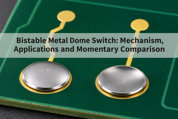
A bistable metal dome switch is designed to remain in either of two stable mechanical positions after the actuating force is removed. That is different from a conventional momentary metal dome, which springs back when released. The practical question is whether the application needs a maintained mechanical state, a maintained electrical state, or simply a momentary pulse: those are not interchangeable specifications.
What Is a Bistable Metal Dome Switch?
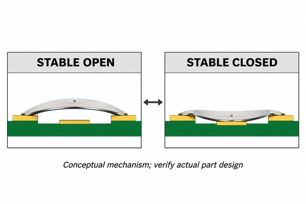
In a deliberately bistable design, the formed spring has two rest positions. An input moves it from one position to the other; removing that input does not automatically return it. A second, correctly directed input is needed to reverse the state, if the part is intended to be reset. The two positions must be demonstrated on the actual specified dome, not inferred from an ordinary dome that stays depressed after damage.
Some bistable metal dome applications use the change of state as a one-time event, including tamper or pressure indication. Others may be designed for repeat switching. Do not assume that every two-position dome has a repeat-cycle rating or that it makes the same electrical contact in both positions. Request the state diagram, permitted actuation directions and cycle requirement for the particular design.
The acceptance language should state whether both positions must persist for a specified dwell time after unloading, and under which temperature and vibration conditions. Without those conditions, “bistable” is too broad to serve as a drawing-level pass/fail requirement.
How Does a Bistable Snap Dome Hold Two States?
A bistable snap dome passes through a change in spring geometry during actuation and settles into another stable position. Unlike a momentary spring that supplies enough return force to recover when the load disappears, the bistable geometry does not return on its own under the specified support and load conditions. The mechanism depends on the formed dome, its boundary support and the direction and location of the applied force.
That description is mechanical. A PCB contact layout determines whether either stable position is electrically open, closed or connected to a different circuit. For example, a dome supported by an outer ring might touch a center pad only in one state. This is a conceptual arrangement, not a promise that every bistable dome can be dropped onto a standard metal-dome footprint.
Momentary vs Bistable Metal Dome: What Happens After Release?
A standard momentary dome is selected when each press should make a contact and each release should reopen it. Its familiar click comes from snap action, but snap action alone does not make a dome bistable. A bistable design is selected only when retaining a mechanical position after the force is removed is part of the function.
The comparison below concerns intended behavior of approved parts. A momentary dome that remains collapsed after an excessive press has not become an acceptable bistable substitute. It has failed its return requirement, and its contact, tactile response and remaining life are not established by the fact that it stays down.
| Decision point | Momentary dome | Intentional bistable dome |
|---|---|---|
| After input force is removed | Returns to its specified rest shape | Retains the selected stable position |
| Next state change | Next press makes another temporary transition | Requires a specified reverse input, if resettable |
| Electrical behavior | Usually open at rest in a normally open PCB layout | Depends on contact and pad design in each state |
| Acceptance check | Return, opening and cycle life | Both no-load states, transition, contact map and required cycles |
Is Bistability the Same as an Electrically Latching Switch?
No. Bistability describes the mechanical positions of the spring. Electrical latching describes a circuit or switch output that remains in its selected state. A bistable dome can contribute to a maintained contact, but only if its contact geometry and mating circuit are designed for that result. A momentary dome can also command a latching electronic circuit without becoming mechanically bistable.
Write the requirement in two lines: the no-force mechanical position after each action and the electrical terminals that must be connected in that position. This avoids ordering a momentary snap dome for a function that needs a mechanically retained state, or specifying a custom bistable spring when a standard momentary key plus electronic latch would meet the actual need.
When Is a Dome Stuck Down a Failure, Not a Bistable Feature?
The answer comes from the approved design. If the drawing specifies momentary return, a dome that remains inverted after release is a defect, even when the electrical contact appears usefully maintained. Excess travel, an oversized or off-center actuator, uneven support and a damaged transition ring can prevent recovery. Our round metal dome series is a conventional product family to compare against a proposed maintained-state requirement; its presence in our catalogue is not evidence that it is bistable.
Check the part in the complete assembly. Enclosure preload or a shifted adhesive carrier can hold a good momentary dome down, whereas a permanently damaged dome may remain inverted even after it is removed. Preserve the as-found stack and compare it with an unused part before assigning the cause. For a detailed failure path, see our separate guide to the inverted metal dome switch; the intended two-state design discussed here is a different task.
Which Applications Need a Retained Dome Position?
A retained position may be useful when a pressure threshold or tamper event must leave a mechanical indication after the initiating force has ended. Published specialist designs also describe normally open or normally closed pressure-switch variants built around a purpose-designed bistable dome. Those examples show a possible use, not a specification for an off-the-shelf dome from our catalogue.
For a normal keypad, remote control or human-interface key, a momentary dome is generally the relevant starting point. If the desired effect is an on/off command rather than a physical retained contact, a momentary key with circuit-level state storage may be simpler to verify. Choose according to the user’s required post-release output and the allowed assembly, not because the word “snap” sounds like a latch.
How Should the Actuator Change Each Stable State?
Specify the direction, location and travel of each input. A push from the convex side might produce the first transition, but the return transition may need access from the opposite side or a separate mechanical feature. If the dome is intended for one-time indication, deliberately omit a reset feature only after the use case and service procedure are documented. A one-sided keypad plunger cannot be assumed to reset a part whose reverse motion needs opposite-side loading.
Support points and hard stops belong in the same review. Too much travel can damage a momentary or bistable spring; too little may not complete the transition. Measure the assembled stack, including overlay, spacer, carrier and PCB, at both states. Check that neither state is being maintained merely by external preload when the design requires the dome itself to be stable.
For a resettable version, verify both force-travel branches separately. A passing first transition does not establish that the opposite-side reset is accessible or repeatable in the finished product. For a one-time version, document how an activated unit will be identified and whether it can be serviced or must be replaced.
What Contact States and PCB Pads Must Be Specified?
Define the terminal pair, contact status and expected resistance or voltage for each stable position. If one position must remain closed, confirm the dome’s contact area, outer support and center-pad relationship under no applied force. If both positions signal different outputs, a simple two-pad footprint is unlikely to express the complete function without additional circuit design. Draw the contact map before selecting the PCB artwork.
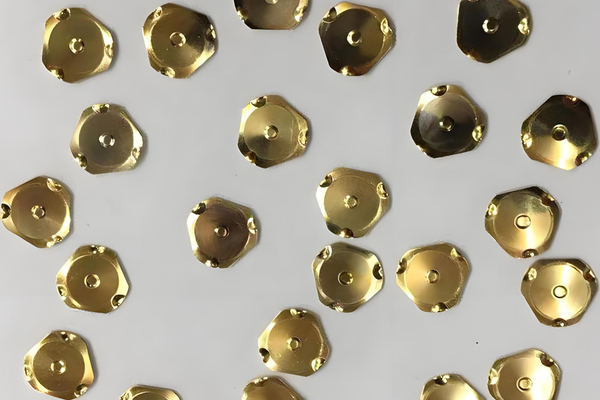
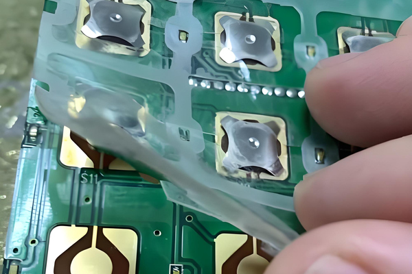
Our four-leg metal dome series illustrates a different support layout from a round perimeter dome. The foot pattern changes the mating pad and adhesive clearances. It does not establish bistability. Where multiple ordinary domes are needed, a metal dome array can place them on a carrier; again, an array does not change the individual domes into two-state springs.
How Do You Test State Retention Without Applied Force?
Set the part in state A, remove the actuator completely, and record its free shape and contact state. Apply the specified transition input to reach state B, remove the input again and repeat the observations. If reset is required, use the documented reverse action and verify the return to A. Repeat at the required temperature, orientation and assembly tolerances; a loose-part demonstration alone is not an assembled-switch qualification.
For a hypothetical normally open sensing circuit with a 5 V supply and a 47 kOhm pull-up, an open contact may read near 5 V and a closed contact near 0 V at a high-impedance input. The calculation is simply 5 V / 47 kOhm, approximately 0.106 mA of nominal pull-up current when closed, before other circuit paths are considered. Those values are an illustrative test setup, not our product ratings or acceptance limits: use the approved schematic, meter loading, contact-resistance limits and actual thresholds to judge the selected design.
Record both the electrical measurement and the visible mechanical state at each stage of the test table. If the geometry retains state B but the output changes after unloading, the failure is in the contact path or sensing circuit, not proof that the spring returned. Conversely, a stable output voltage cannot prove the spring is stable if the actuator or a short is holding the circuit closed.
| Test stage | Condition to record | Evidence of intended function |
|---|---|---|
| Initial A | No external load; actual assembly | Specified shape and contact map A |
| A to B | Input direction, travel and force | Complete transition without damage |
| Released B | Input removed; dwell time specified by project | Shape and contact map B persist |
| Reset, if required | Approved reverse input | Return to A and specified electrical state |
| Life test | Specified cycles and environment | Both states and transitions remain within approved limits |
What Can Invalidate Bistable Behavior in an Assembly?
Even a deliberately bistable loose spring can behave differently when the carrier film, adhesive, actuator and PCB constrain it. A film may pull the dome back toward one position; a housing rib may hold it in the other. A center pad or solder-mask feature may block full travel. Test the retained positions with the complete stack and with the actuator fully disengaged, including the worst-case dimensional combinations.
Contamination or oxide can also make the electrical result disagree with the mechanical position. Separate the observations: inspect the free dome shape, measure the contact state, and verify the input circuit. A stable shape with intermittent contact calls for a contact and PCB investigation, whereas a contact that stays closed only under enclosure preload calls for an assembly investigation.
How Do You Choose Between a Standard Dome and a Custom Bistable Design?
Start with the required post-release behavior. If the key must reopen after every press, select a conventional momentary part and verify tactile force, travel, return and electrical life. If the mechanism must retain two free positions, document both states, how each transition is driven, whether reset is required, contact mapping, operating environment and cycle life. Ask for a purpose-designed and qualified part rather than trying to create bistability by over-travelling a standard dome.
At EBest Circuit(Best Technology), we offer conventional metal dome and dome-array product options on the pages linked above. Our published product information does not establish an off-the-shelf bistable dome specification. Send us the required state diagram, PCB layout and actuator stack if you want us to check whether an appropriate verified solution is available; do not treat a catalogue shape or this conceptual illustration as approval for a maintained-state function.
If a vendor proposes a custom bistable part, request a sample tested in the final stack against the agreed state-retention, contact and life criteria before treating the proposal as interchangeable with a stocked momentary dome. That qualification step is especially important when the application depends on a no-power indication or a maintained safety-related contact.
Bistable Metal Dome Switch FAQs
Can an ordinary snap dome be bistable?
Snap-through during a press is normal, but an ordinary momentary dome must recover on release. If it stays inverted, compare the actual part drawing and assembly before calling it an intentional two-state design.
Does a bistable dome always keep the circuit closed?
No. The two mechanical positions do not define the electrical output by themselves. The contact geometry, PCB pads and wiring determine what each position does.
Are bistable domes always reusable?
No. Some designs are intended as one-time indicators; others are resettable. Specify the reverse action and verified cycle life for the chosen part.
For a two-state requirement, send sales@metal-domes.com the mechanical state sketch, contact truth table, actuator direction and life target. We can review the request against our documented product options and identify what still needs qualification.
A bistable metal dome switch is defined by its verified no-force states, not simply by a dome that remains down. Make that distinction explicit in the drawing and acceptance test before committing a PCB footprint or enclosure stack.