How to wire an automotive switch? This blog covers types, working principle, wiring guide and considerations, supplier selection guide for automotive switch.
What Is Automotive Switch?
An automotive switch is an electrical or electro-mechanical component installed in vehicles that allows drivers and passengers to manually or automatically control circuits, input signals, select functions, or change modes. It serves as the primary physical interface for interacting with the vehicle’s systems, enabling the operation of essential features like lights, windows, climate control, infotainment, driving modes, and various safety functions.
Types of Automotive Switches
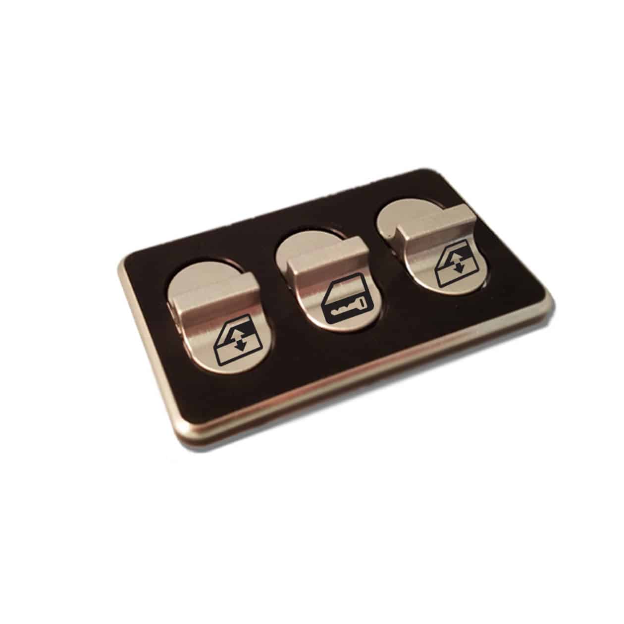
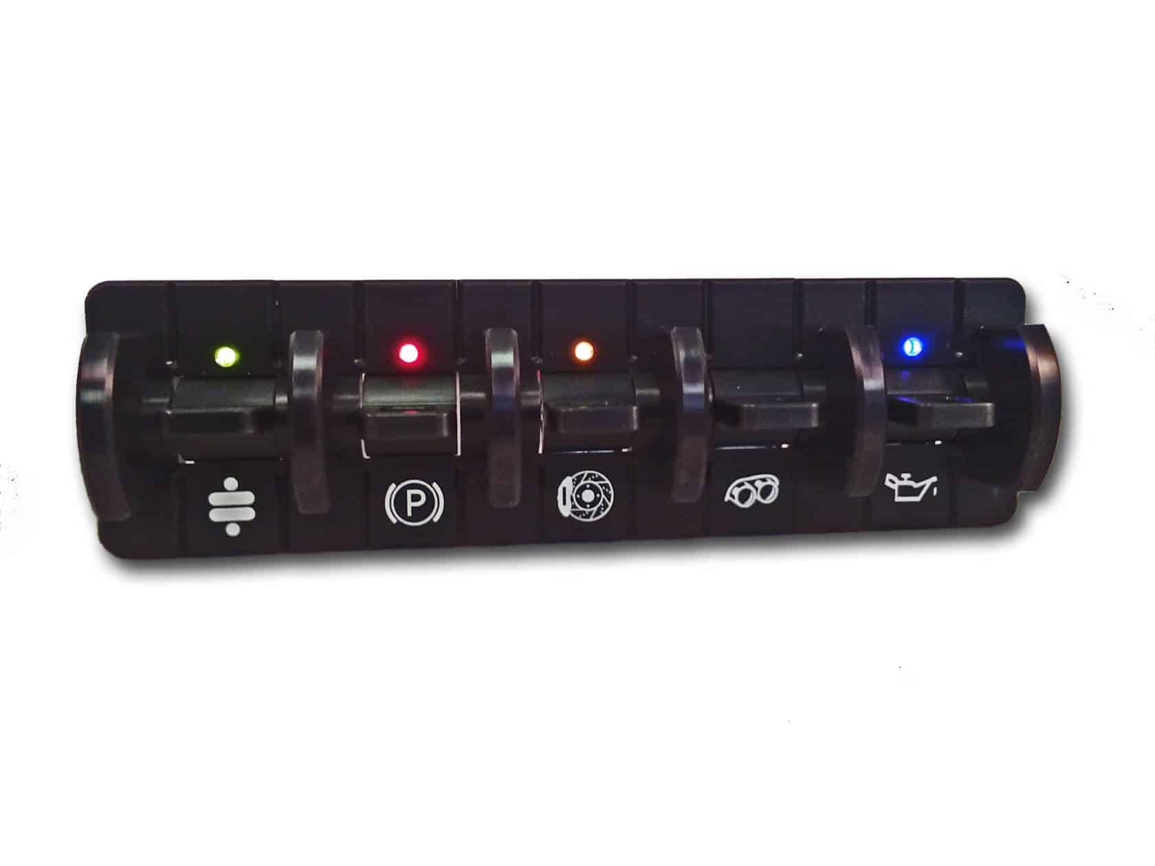
- Rocker Switches: Control circuit on/off by rocking up and down, commonly used for basic functions like windows and doors.
- Push Button Switches: Light press to trigger, often used for high-frequency operations such as starting/stopping the engine or air-conditioning control.
- Rotary Switches: Adjust gears by rotating, commonly seen in scenarios like lighting control or volume adjustment.
- Touchpad Switches: Integrated into the central console screen or specific areas, supporting interactions like swiping or pressing, mostly found in high-end models.
- Dimmer Switches: Used for stepless brightness adjustment, such as interior ambient lighting or instrument panel backlight.
- Lever Switches: Controlled by lever action, e.g., wiper gear adjustment.
- Toggle Switches: Traditional mechanical switches, such as old-style headlight controls.
- Knob Switches: Adjust parameters by rotating, e.g., air-conditioning temperature or airflow control.
- Special Function Switches: Customized switches for specific purposes, such as rearview mirror folding or seat memory functions.
How Does An Automotive Switch Work?
Mechanical Switches: Manual-Electromagnetic” Dual-Mode Control via Physical Contacts
- Manual Main Power Switch: When the knob is rotated to the “NO” position, internal copper contacts close, allowing current to flow and power the entire vehicle (e.g., manual power-off switch in fuel vehicles). Rotating to “OFF” separates the contacts, cutting off power. Simple in structure but requiring manual intervention, commonly found in basic models.
- Electromagnetic Power Switch: When the coil is energized, it generates a magnetic field that attracts the iron core to close the contacts (e.g., during engine start). Upon power loss, the spring resets the contacts to open. Fast response and high reliability, widely used in modern starting systems.
- Combination Switches (e.g., turn signals/wipers): Internal moving/static contacts are altered via handle movement. For instance, when the turn signal lever is shifted to left/right, corresponding contacts connect, allowing current to flow through the flasher unit to flash the bulb. Wipers control motor speed via different positions for intermittent, low, or high-speed operation. Intuitive operation but subject to mechanical wear.
Electronic Switches: Precision Regulation via “Induction-Signal” without Contacts
- Hall Effect Switch: Based on the Hall effect principle, when a magnet moves with the gear lever to positions P/R/N/D, semiconductor materials sense magnetic field changes to generate a voltage difference, triggering the ECU to execute gear-shifting commands. No mechanical wear, with a lifespan of hundreds of thousands of cycles, commonly used in electronic shifters.
- Electronic Power Switch: Monitored by the ECU for system load, automatically adjusting current distribution and preventing short circuits. For example, in smart cabins, devices like screens, audio systems, and seat heaters are powered on demand via power switches, with the ECU continuously monitoring current and voltage data to ensure safe operation, enabling precise “demand-based power supply” control.
Intelligent Control: Closed-Loop “Signal-Decision-Execution” System via Bus Collaboration
- Regional Architecture: Electrical components in each zone connect to the ECU via signal buses, with the ECU acting as the “intelligent brain” to integrate sensor, switch, and actuator data. For instance, pressing the AC switch triggers the ECU to engage the compressor clutch, driving refrigerant circulation for cooling. In collisions, the ECU immediately cuts high-voltage circuits to prevent short-circuit fires.
- Intelligent Temperature Regulation: Bimetallic thermal switches bend via thermal expansion differences to close contacts (e.g., activating the fan at 95°C water temperature). Wax-actuated sensors expand in liquid form to push rods for contact control. Thermocouples use resistance changes for the ECU to determine water temperature, achieving precise control.
- Safety Protection Collaboration: Abnormal temperature switches trigger alarms and switch to safe modes. Electronic power switches automatically cut power upon detecting current anomalies, forming a “fault self-diagnosis-safety isolation” protection chain.
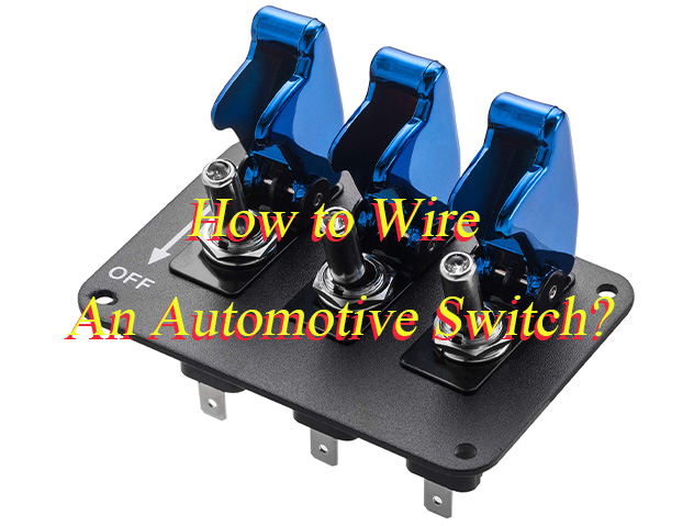
How to Wire An Automotive Switch?
A detailed guide to how to wire an automotive switch:
1. Preparation and Safety Verification
- Tools required: wire stripper, screwdriver, multimeter, insulating tape, terminal connectors, electrical gloves.
- Power-off procedure: Disconnect the vehicle battery’s negative terminal. Use a multimeter to confirm zero voltage, preventing electric shock or short-circuit risks.
- Circuit diagram reference: Check the vehicle manual or repair guide to identify switch pin definitions (e.g., ignition switch pins 30/50/15/ACC; headlight switch power/control lines).
2. Wire Identification and Terminal Preparation
- Locate switch position: e.g., steering column (ignition switch), dashboard left (headlight switch), or battery vicinity (main power switch).
- Strip wires: Use wire stripper to remove 10-15mm insulation without damaging internal conductors. Cover exposed sections with heat-shrink tubing or insulating tape.
- Terminal matching: Select appropriate connectors (e.g., fork terminals for bolt fastening, ring terminals for plug-in switches) based on switch terminal types.
3. Wire Connection and Fixing
- Power line connection: Battery positive ? ignition switch pin 30 (constant power), protected by a fuse (e.g., 10A) to prevent overload.
- Control line connections:
- Ignition switch: Pin 15 (ON position) connects to instrument/ignition systems; pin 50 (START position) connects to starter relay.
- Headlight switch: Low-beam control line connects to relay input; fog lights require headlights activated first.
- Main power switch: Series-connected to battery positive main circuit; output connects to vehicle electrical system positive.
- Grounding: All device negatives connect to vehicle chassis ground. Ensure clean, rust-free contact surfaces and proper torque (e.g., 5-7N·m).
4. Insulation and Protection Measures
- Wire fixation: Secure wires with clips or zip ties along the frame, avoiding friction with moving parts (e.g., steering column, suspension).
- Reinforced insulation: Wrap connections with 3-5 layers of insulating tape, focusing on exposed metal parts to prevent short-circuits or leakage.
- Waterproofing: Use waterproof junction boxes or heat-shrink tubing in humid areas (e.g., chassis wiring) to block moisture ingress.
5. Function Testing and Acceptance
- Resistance check: Measure switch resistance with a multimeter (?0? when closed; infinite when open) to confirm good contact.
- Power-on test: Reconnect battery and verify switch functions (e.g., headlight on/off, engine start, device power supply).
- Troubleshooting: If malfunction occurs, check for loose connections, blown fuses, or poor grounding. Use test lights for segment-by-segment fault diagnosis.
Automotive Switches Wiring Considerations
1. Safety First Principle
- Always disconnect the vehicle battery’s negative terminal before operation. Confirm zero voltage with a multimeter to prevent electric shock or short-circuit risks. Wear insulating gloves throughout the process; no live work is permitted.
2. Wire Gauge Matching
- Select wire gauge based on load power: thick wires (?4mm²) for high-power devices like starters; 0.5-1.5mm² for low-power signal lines. All circuits must be protected by fuses (e.g., 10A) to avoid overload burnout.
3. Reliable Grounding
- Device negative terminals must connect to the vehicle chassis ground. Clean paint/rust from grounding points to ensure direct metal contact. Tighten bolts to 5-7N·m torque to prevent loose connections that increase resistance and heat.
4. Wire Fixation & Protection
- Secure wiring along the frame/interior using clips or zip ties every 20-30cm, avoiding moving parts (e.g., steering column, suspension). In humid areas (e.g., chassis), use waterproof junction boxes or heat-shrink tubing to block moisture.
5. Strict Adherence to Circuit Diagrams
- Wire color codes vary by model (e.g., red for positive, black for ground). Always refer to the vehicle’s circuit diagram in the manual/repair guide. Clarify ignition switch pin functions (30/50/15/ACC) and headlight switch logic (low-beam/fog light activation sequence).
6. Function Verification & Troubleshooting
- After wiring, measure switch resistance with a multimeter (?0? when closed; infinite when open). After reconnecting the battery, test functions systematically (e.g., headlight on/off, engine start). For faults, use a test light to check loose connections, blown fuses, or poor grounding.
7. Special Switch Requirements
- Ignition switch: Differentiate “ON” (pin 15 for instruments) and “START” (pin 50 for starter relay). Main power switch must be series-connected to the battery positive main circuit to control overall vehicle power.
Welcome to contact us if you need any help for automotive switches: sales@metal-domes.com